
rgordon
USA
Asked
— Edited

Robot Arm Designs
Anyone interested in creating a team to brain storm ideas and designs for robot arms for large or small robots. Perhaps collectively we could come up with a universal design that many of us could use. We each could provide input, drawings and/or services.
Rex

I like it. I have a design for my small B9 where each arm will use 4 servos but only 3 ports on the EZ-B. I think it will give me a very similar movement to the real B9 and have the claws too.
Bret
Thanks for responding Bret. Do you have any drawings or pictures yet?
I am going to get together all my pictures and drawings that I was working on for Magnus and post them soon.
I also like this idea, @rgordon. I struggle with mechanical designs and implementation. I'm software, by profession, not hardware! eyeroll
A universal design would be great! What I'd be looking for in an arm design is something that's simple electrically and mechanically, but reasonably strong. Maybe strong enough to pick up a deck of playing cards or your favorite carbonated beverage?
For example, a DIY linear actuator using a screw thread, a nut, and a motor/360 servo seems like a strong/effective implementation to me. But what do I know?
I would be interested in this too!
A few weeks ago the family and I went to Wolf Lodge and there was a robot arm ice cream machine that made you a sundae with your favorite toppings! Now the whole family wants one, including me! Anyway, I would love to work on a design like this..that would be reasonably priced as well.
v/r
Kevin
I think we all have enough combined talents to achieve something useful. I may need lots of help when it comes to programming.
I am using a DIY linear actuator design for T.E.C.H. Although I think it could be simplified a little more by using a small cordless screwdriver which already has the gears built in. It all depends on the size arm you need for your bot.
I'll try to make up some drawings and get them uploaded. My idea for my B9 hack is two servos tied together to make a bending motion so I can get 90 degrees in either direction. Then one servo to operate his claw, and a final servo to twist the entire arm. As B9 doesn't have shoulders it actually makes it a little easier. I will work on some drawings this week.
Super....I am working on drawings for the arm I am building for T.E.C.H. I guess you would call him a medium sized robot?
test...test
just wanted to see if I could post a decent looking drawing.
If you don't have it already, a good free drawing program is
emachineshop
It's a free download. I just use it for drawing. Their prices are too high for actually machining the parts. The reason I like using it is because it so easy to draw parts to scale and print them out as actual size. It has lots of cool things you can do to make drawing easier. Keep in mind it is mainly used for drawing individual parts and not say for instance a complete drawing of your robot. 100 times easier than learning Auto-Cad.
After I create the drawing I use software called Print Key 2000 to take a snapshot of my screen then it lets me save it as a .jpg file so I can upload it here.
Okay, I'm a little more old school so here are some drawings:
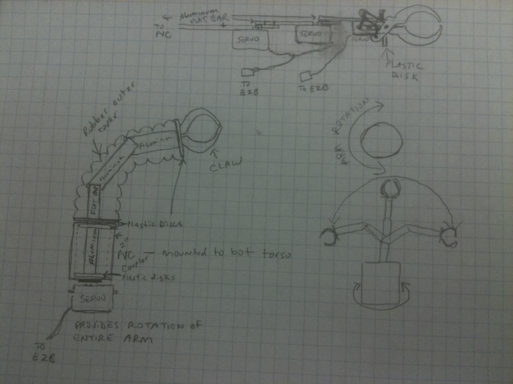
This is the whole unit that would protrude from the front of B9 - I am using 2" PVC coupling as the arm sockets.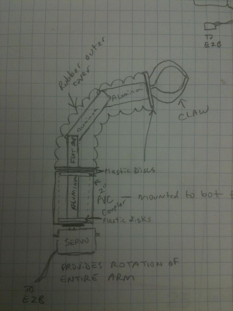
Mounting some plastic disks to aluminum flat bar and then the whole thing spins preely inside the PVC. I can use a servo to rotate the whole assembly. Then off that are two more pieces of flat bar attached to two servos for bending motion. The two are tied together off one port (with a Y extension) so work in unison. It is important to make sure they are going the same way so they move the same direction.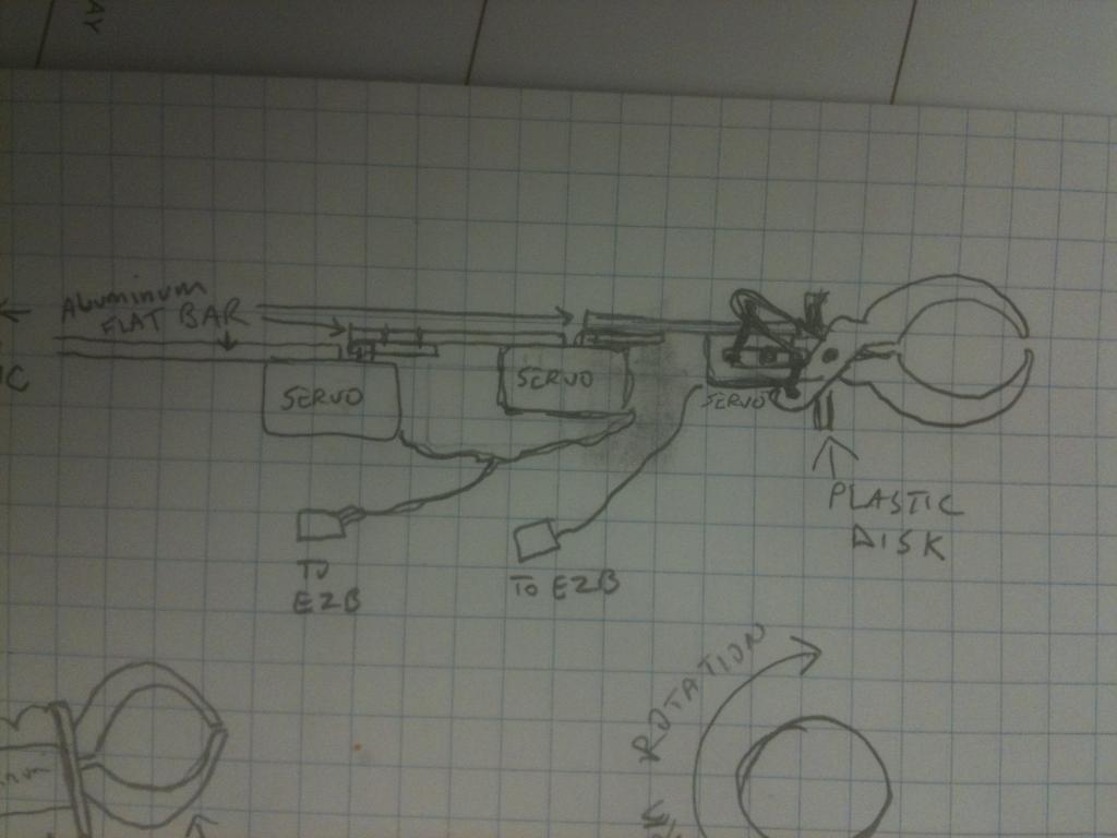
Then I have a claw mounted on the end disk and use a scissors motion to open and close with my micro servo. As you rotate the whole arm, the claw will rotate too. I am using a rubber air supply line from a filter mask as a covering because of it's flexibility with minimal resistance.What do you think?