
PRO
dbeard
USA
Asked
— Edited
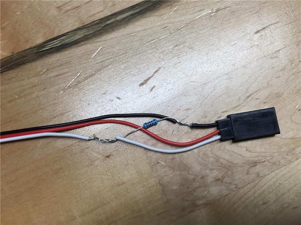
I have a switch that is always closed. If it becomes open that is a condition that I take some action. I put together a pull down resistor (based off the attached picture from another post). But I noticed that it gets really warm to the touch. Is that expected? Should I use a larger resistor (or smaller).
Thanks in advance.
I have smaller resistors.
I am not an electrician either and browsed many threads talking about the pull down resistor.
So is my solution to install a smaller resistor and make sure the GND and White goto the switch.
My switch has two wires. I want to set it up so that as long as the button is pressed so switch is closed I take no actions, but if the switch is open (or no longer pressed) I want to take an action.
To avoid doubts:
P (Watts) = I * I * R = V * V \ R
P = 7.4 * 7.4 \ 47 = 1.16 w
your resistor can handle 1/2 = 0.5 W, so eventually will get harm and then black smoke.
P (Watts) = I * I * R = V * V \ R
P = 3.3 * 3.3 \ 1000 = 0.01 W
P (Watts) = I * I * R = V * V \ R
P = 3.3 * 3.3 \ 4700 = 0.002 W
Like i said i use 4.7K but it can work with 1K, the consumption is not relevant.
Note: you can use the 47 ohm:
P (Watts) = I * I * R = V * V \ R
P = 3.3 * 3.3 \ 47 = 0.2 W
You are wasting 0.2W it's your battery
One more stupid question. I want to wire with the button pushed, so it will probably be pushed most of the time. Will this be an issue or if I have it wired correctly with the right resistor I should be OK?
And some low level heat is expected just based on the way a resistor works, but it shouldn't be to hot to handle, correct?
1) always open (Input Pin = GND)
2) Pushed (Input Pin = 3.3 and power consumption)
If you keep the button pushed for a long time, makes sense a weak resistor to avoid battery draining, and is expected the heat dissipated but with 1/2 W or 1/4 resistors you can't fry anything
If you want a different logic e.g. always closed, I would work the logic at the script level, to avoid power consumption.
VCC = ideal 3.3v, no more than 5V.
Resistor = same rules
@Dave:
I believe you can use that logic for robot bumper switches, imagine the robot hits the wall.
If the idea is to monitor switches states, can be problematic if the verification code takes longer and misses a transition.
It is a stationary robot and I am using to determine if it gets lifted, knocked over, etc..
you're right, my initial concern was the voltage on the red pin, before serious damage.
but i missed something:
I would change the wiring (post 19)
I have 6 bumper switches, 3 front, 3 back, you have more digital ports than analog ports so why not ?
@dbeard
Can you provide more details ? you have our attention
Trying to understand.
I know you must be getting tired of me. But I have a question about post 19.
So there are 3 pins coming off of the EZB. Black Red White, with Black being ground, Red is VCC, and white is signal.
So based on your drawing the Switch gets connected to Black and White.
I put the resistor on Red and connect inline with the white pin.
1) disconnect the cable/plug mod you showed in the picture from the Digital port
2) connect the cable/plug mod to ADC port 0
Voila.
It would be really cool if one of the electronics people would put together a tutorial on this. I think there is some assumed knowledge around electronics that some of us don't have, especially how this wiring stuff relates to the ports on the EzB.
PTP - Thanks for you time and hanging in there with me. I appreciate the help.
Also, thanks to everyone else who jumped in and added support.
Code:
I agree. A tutorial on pull up/pull down resistors and why and where they are used would be great.
Alan