Asked — Edited

Need Help Wiring Remote Control Lawn Mower

Hi all,

This is a great forum and I am glad I found it! I am working on a 4wd remote control mower build. Here is what I have: 20 hp electric start briggs gas engine DX5E controller 2 battle switches sabertooth 2x60 motor controller 2 x wheel chair motors

This is the second remote mower project, the first one turned out great but it did not have electric start or electric deck adjustment. I need help figuring out how to wire the starter to start the gas engine via the remote. I also need help wiring an electric screw jack to be able to adjust the deck height up and down via the remote control. Any help would be GREATLY appreciated.


ARC Pro

Upgrade to ARC Pro

With ARC Pro, your robot is not just a machine; it's your creative partner in the journey of technological exploration.

#2  

You will need a relay to power the motor switch. You will need some additional circuitry between the digital port on the EZ-B and the relay. There are a few threads on the forum about how to wire this up. Do a search on: transistor relay switch and the most useful ones pop up.

Alan

#3  

Not to sound totally ignorant, but that flew right over my head. My knowledge is really in fabrication. I am learning more about the wiring etc but far from knowledgable

#4  

The gas briggs engine was originally an electric start engine that started off of turning a key switch on the mower. We need to delete the key switch and be able to start and turn off the gas engine via the DX5E controller. I was told that I could add a starter solenoid and wire a battle switch to the solenoid to start the engine, but what I am worried about is that the battle switch is a 10 amp switch. I was also told I could use the second battle switch to shut the motor down by wiring it to the original kill switch? As far as the electric screw jack its my understanding that I can use a double pole double throw relay to be able to adjust deck height? Am I on the right track?

#5  

I am not fully versed on electronics myself, but am researching the same thing for some of my bots components, so this is what I found. Basically, a relay can be used to switch a higher voltage or amperage from a low voltage or amperage signal source, so you would replace your switches with relays. The problem is that the ports on the EZ-B are too low amperage to directly drive a relay without burning out the board, so you need a transistor as an additional low to higher power switch (and probably a diode to further protect the EZ-B.

There are some relays specifically designed for this kind of thing. If you look for Arduino relays you can find them, but I think you will spend less and learn more building the circuits yourself.

Hopefully someone else will chime in with more specific instructions.

Alan

United Kingdom
#6  

Alan is right.

Basically, and put in to layman's terms as best I can...

To switch something which uses higher current/power than the EZB you need to build a circuit.

First, you need to make the switching circuit, this is the TIP122 Darlington Transistor Circuit used for millions of reasons with the EZB. This is the typical diagram for this part of the circuit User-inserted image

What this does is, it takes the signal from the EZB and when a digital on command is given through ARC, EZ-Script, SDK or whatever you use, it will allow current flow from the VCC to the Ground.

The next part is to add in a relay to the circuit, you wont be connecting the above direct to the mower.

A relay basically allows low voltage, low current control circuits to control larger circuits. When the control circuit energises the relay it closes a switch allowing current to pass.

Sort of like this; User-inserted image

That should take care of activating the mower circuits from the EZB. Hopefully it was simple enough to understand how it all works...

For an example of how to use the EZB to switch 110v circuits check out Josh's Salt Water Tank project

#7  

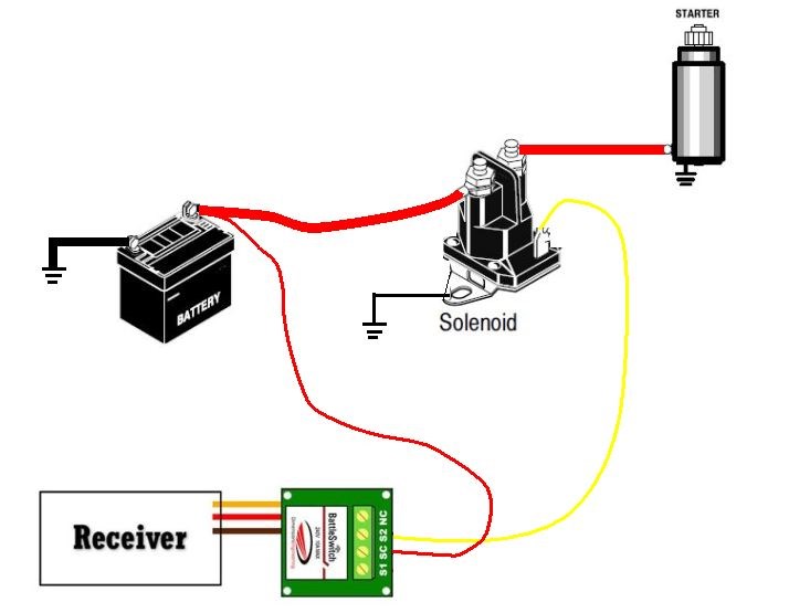
The Battle Switch can be activated from an EZ-B servo port. It uses a servo signal to activate it. I have one hooked to the AUX channel of my Spectrum DX6 rcvr and use the toggle switch on the transmitter to turn it on or off. Works great. Below is a copy of the description from the Robot Shop web site. You must make sure that 10A is enough for activating your starter motor . EDIT I mean the starter solenoid.

"Relay can activate applications with voltage levels as high as 240VAC (10A @ 28VDC) . Toggled via hobby radio control gear. . Control powerful auxiliary weapons!

Dimension Engineering BattleSwitch Radio Controlled Relay is the larger, 10A version of the popular PicoSwitch (RB-Dim-02). BattleSwitch is a relay (SPDT) switch that you toggle via hobby radio control gear. You can use BattleSwitch to quickly and easily control glow plugs, BattleBot weaponry and more. You can activate applications with voltage levels as high as 240VAC without having to know anything about microcontroller logic levels or transistors because the relay offers full electrical isolation from your receiver electronics.

The Dimension Engineering BattleSwitch plugs into a standard hobby radio control receiver as easily as a servo does. You connect the load that you want to toggle using BattleSwitch's wear resistant screw terminals. Depending on the channel you use, you will then be able to control the relay by moving your radio's control stick up or down, left or right, or another method you desire.

BattleSwitch has a status LED on the bottom. The LED will light up when the relay switch is on, and vice versa. It will also tell you if your radio link is too weak by flashing repeatedly. The relay is a single pole double throw switch. Its typical lifetime is 100,000 switching cycles, depending on how heavy a load you are using. "

RobotShop.com

Diagram from Dimension Engineering

Dimension Engineering.com

#8  

I had not heard of a "Battle Switch". That sounds like a great solution.

Thanks Rich for the circuit diagram and explanation for using a transistor and relay too.

@jstarne1, if you are reading this, another couple of good posts for the Wiki.

Alan

#9  

This is the switch/relay i was talking about... Will it work?

http://www.robotshop.com/dimension-engineering-battle-switch-1.html

#10  

On a side note, If I use the Battle Switch, I obviously wire it to the Solenoid, seeing that I can not find the Amp rating or pull of a standard Ford style solenoid will the 10 amps be enough?

#11  

RichMR2,

Thank you for the diagram. I am thinking I need to run a battle switch to the starter solenoid, then wire the solenoid to the starter?

#12  

"Thank you for the diagram. I am thinking I need to run a battle switch to the starter solenoid, then wire the solenoid to the starter?"

This sounds correct. Do you own an ammeter? If you haven't disassembled the existing mower completely yet, you could measure the amps at the solenoid while starting the motor to make sure it is drawing less than 10 amps.

Does it start with a battery or a 120VAC plug today? If a battery, it is almost certainly less than 10 amps draw.

Alan

#13  

Why not use a standard automotive relay 12v coil spdt 30 amp continuous rating. They can handle twice that for several seconds. Yes I'm watching for wiki material;) I have been away from the keyboard a few days but I'm back now.

@ Alan 90 percent of meters out there under 300 bucks are fused at 10 amps max for measuring current load even the nicer "ideal" "snap on" and "fluke" brand meters its a standard limitation. Just wouldn't want someone to let the magic smoke out of their meter... It needs it after all lol

#14  

Just out of curiousity why use a coil? A coil is to supply ignition spark, I need to engage a starter?

#15  

Last summer my John Deere walk behind transmission took a crap. I can't complain though as it lasted me 26 years:) I seen some robotic mowers on the net and it really only takes a hand full of parts to convert a mower to RC control. I plan on using a regular mower, maybe if I had that machine shop you have I would go from scratch too:) I was wondering how you plan on turning the mower as your wheels looked fixed? I know one of the problem RC controlled mowers have is they don't run true.

Herr

#16  

Differential drive just like a skid steer, if you have turf tires it will not harm the grass

#18  

http://s825.photobucket.com/albums/zz175/real57vetteguy/?action=view&current=2013-02-15_19-15-37_373_zps4a2d0895.mp4

#23  

You might want to replace the 2 rear wheels with caster wheels so you don't tear up the grass when it turns

#24  

Would that not defeat the purpose of a 4WD mower for steep inclines? If I want it to be gentle on the turf I can install smooth turf tires, this is a purpose built mower for high grass on STEEP inclines! This is the second of 2 builds, the first one has smoother tires but the same type of drive, it does not harm grass or turf in any way. This one will tear up some grass if your our doing donuts in the middle on the lawn or if you don't know how to operate it properly, remember it doesnt matter if you run it in forward or reverse, it has the same amount of power in both directions, so 90% of what I am mowing is straight up and down, no turning!

#25  

on using a switching circuits with your design i would look at mosfets can handle very high current

Some well over 35 amps and more and almost no heatsink is needed like with switching darlingtons

USED 100 WATTS mosfets without a heatsink for H-BRIDGE design and not like switching transistors you can easy add in parallel to double the current rating with switching transistors (darlingtons ) YOU NEED A FEW RESISTORS with mosfets none is needed

Second i am looking at building a robotic mower ,but with our gas for many reasons,need a very very big battery larger frame ,plus very powerfull drive motors

BUT still you project does look good

#26  

Look at rc esc they work great an cheep

#27  

Simple $5.00 mosfet circuit or less is easy to make and easy handle 25 amps and no heatsink ,RELAYS not a great idea,cost is high plus you need a switching circuit if using a 25 amp darlington switching circuit you will need a good size heat sink

IRFZ44 mosfet is so simple to use ,it hooks the same as switching darlington circuit and resistor value is same,and no heatsink is needed,plus no power is wasted

#28  

pittom i see i am not the only one that doesnt use spell check and RICH has said to me a few times

#29  

lol especially when it is late

#30  

I don't want to drag this off topic, but since you brought it up. @robotmaker, it has been much easier to understand what you are saying in the past week or so since you have been checking your spelling and grammar. I had gotten to the point where I just skipped your posts because I never could figure out what you were trying to say, but you are much easier to read now, so thank you.

One extra hint that I have used to help people who sometimes have trouble communicating in writing.. Read your posts out loud before you hit send and make sure they sound right. It can help when you are typing so fast you get your words out of order. Just reading silently doesn't seem to do it, but reading out loud you actually hear yourself and can notice more. (I planned on telling you this privately when I asked you to email me a few weeks ago, but you wouldn't, so here it is...).

Thanks for your recent information on mosfets. It led me to look up some information and they seem to be very useful.

Alan

#31  

YES i know ,been awhile since i did any good writing and started to slowing comming back to me

This forum is first time i did any writing in over 20 years,never really had the need too.

I have a lot of work and dont really have the time to recheck my spelling or grammar and some is not needed ,like periods and capital letters

But my posts are getting better ,and most likely to make easy to understand them will do a few posts and not put many words in them.

Also of my words i use are very technical and most here dont know what it meens. like RDS on mosfets not many knows what it meens .

MOST think i am wrong on the mosfets,yet i know more about them then most of the guys here .

#32  

We are almost complete with one hang up. I used a battle switch to operate the solenoid for the starter on the gas engine. The switch is rated at 10 amp on 24V and 5 am on 12V. It operates the solenoid correctly but once the solenoid is wired to the starter it fries the battle switch. I am sure it is pulling to many amps but I havent seen a battle switch rated for higher amps? Any ideas?

#33  

Hi "real57vettguy", Sorry to hear that you fried the battle switch. Did you ever identify a solution? Please post! I'm trying to do something similar. Thanks

#34  

This thread is more than a year old, so chances are he has resolved his issue and moved on... I doubt he would be monitoring this thread anyway...

#35  

@realvetteguy - maybe you should post your electrical schematic, that way when you speak of things like battle switch, others can see, what it is, how you are using it and what it does. Then others can see what your doing and offer advice on how to modify what you have going. It is like a road map, you can probably get more advice on how to tweek your electrical system if people can see where your at and where you are trying to go. Rich and others have been talking about pcexpress and 123 schematic programs. And they are free. Btw, I like your project. My 2 cents. :)

#36  

:)Can you tell us where you obtained the tires and wheels? I have a steep slope and have not been able to come up with solution for grip. Thanks, bc :)

#37  

This is an old thread and sadly I haven't seen some of these people around for a while.

However servo City has a good selection of wheels and tires that may be what youe looking for:

Off Road Rubber Tires

wheels

#38  

I to am building a remote controlled lawnmower like @realvetteguys. Like him I am a little stuck on the starter set up as well. I've seen the set up that he was talking about using the battle switches as well. There is no wire diagrams and very little explanation of how it is wired up though. I do know that the example that is shown is using a 12v relay, not a starter style relay that is normally open as a safety system in case it looses signal to the receiver. It is a strictly RC system. He is not using an EZB. This is also how I am starting mine. Eventually I want to convert it to be more autonomous, but right now I will be happy to just get it to work. I have been playing around with the idea of another motor controller to operate the starter. I don't need the pwm though. A relay would probably be best, I know. Obviously, since the mower already has one, It's a matter of actuating it until the engine starts, then shutting it down. My system uses a 6v battery to start it. I can't tell you the amperage; haven't found any specs on it , and I haven't tested it yet. I am wondering if a LM298 motor controller could be used to actuate the relay? Especially since it is only 6v. Hearing he blew the battle switch, I'm afraid to try it on mine. I haven't tried anything as of yet, due to lots of overtime at work and waiting for parts to arrive. But tomorrow I'm off and that is one of my top projects. I'm going to try the LM298 to see, unless someone has a better idea.

#39  

Hi @Rod I am not sure how @real57vetteguy had his wiring hooked up but seems to me the Battle Switch should work fine to pull in the solenoid coil. The Battle Switch contacts are rated high enough to be used to activate the coil of the solenoid.

User-inserted image

#40  

Thanks This is exactly what I was searching for. I'll let you know if it works as advertised.

#41  

Rod did this illustration work for your mower with the battle switch??

#42  

Question.... rgordon...that diagram was exactly what I needed as well... can u also give me diagrams for kill switch and electric clutch using battleswitch with 12v system

PRO
Synthiam
#43  

kwalker - what ezb controller are you using? Some of them can have a kill/safety switch for losing wifi or signal

#44  

I am new to this and really know nothing... the controller that seems to be most popular is the sabertooth 2X32 or 2X60.......or can I wire directly from the battery to the battleswitch...thanks for you patience.... not really versed in electronics....

PRO
Synthiam
#45  

That's a motor controller, not the microcontroller. You'll need a micro of some sort to receive the program and instructions from the software that makes the robot move. The most popular of the ezb's people use for this is the EZ-Robot EZ-B v4. But, if the robot has the computer mounted on it, then using an arduino is fine as an ezb. The best computer to mount on the robot with a camera is the latte panda (i prefer)