
SnowGnomey
USA
Asked
— Edited
Motor Shield Help
I have a Anduino Motor shield and was wondering if any one could help me or or point me in the right direction ,heres the link. I have tired for day trying and no luck! Thanks Motor shield Link

just a word to the wise....................................we don't use the "A' word on EZ-B........................
I've never connected one of those to the EZ-B. But i'm sure it will be pretty straight forward according to those instructions. In ARC, use the HBridge Movement Panel. Select the pins that you chose for the movement. You can also select the PWM pins too That will be an easy add-on!
Thanks DJj, I got It going but now the issue I'm having is with the Movement Panel script. Is it possible to toggle 2 digital ports?t
Hi... I'm also thinking about use an "A" motor shield.. I got two from sparkfun.. But since they are designed to fit as a shield on the "A" board... I have no idea how to hook that on ez-b... I intend to use that to drive two 12v dc motors that will give mobility to my prototype.. Can you help me ? Thanks
Hi... I'm also thinking about use an "A" motor shield.. I got two from sparkfun.. But since they are designed to fit as a shield on the "A" board... I have no idea how to hook that on ez-b... I intend to use that to drive two 12v dc motors that will give mobility to my prototype.. Can you help me ? Thanks
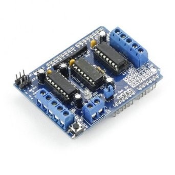
This is the shield i'm talking about...
Hello, I have the same shield, no idea where to connect the signal wires. I've tried about everything I could think of... no result, at all. Has anyone succeeded in the meantime ?
I found this tutorial for a shield using the same chip and that seems to have the same architechture, I'm sending it in case someone more ingenious could make something out of it. It seems, however, that this shield will respond only to IDK programming through arduino board...
https://www.ladyada.net/make/mshield/use.html
From a quick look...
DirA and DirB (12 & 13) look to be direction of the motor. Usually these work that high is one way and low the other. A simple Digital on/off (or Set(port,on/off)) should do that.
PWMA and PWMB (3 & 11) for speed control of each motor, PWM on each of the ports to set the speed.
BrakeA and BrakeB (8 & 9) to apply a brake to the motors (not really required), apply a high to these to instantly stop the motor.
That is assumption, check it out first. But it does look very much like the Dagu 4 motor controller. Check my cloud uploads for an example project for controlling these. There is a Dagu topic too which has more info in than I've put above...
Edit: added links.
Edit 2: Let me know how you get on with the above, I'm always interested in knowing if what I've advised has worked or not but often people don't give the feedback (for whatever reason).