
Asked
— Edited
Motor Controller Signal Voltage
When you hook the motor controller to the ez-b, what is the max voltage that can run on those connections of the motor controller. Do I need to regulate it or can I keep 12v through the ez-b on it?

Don't quite understand what you're doing. The EZ-B V3 is regulated @ 5vdc. Normally the H-bridge controllers are privately powered using a separate battery and the EZ-B is used to only control the signal leads.
If you check my tutorial it explains the connections.
The power which drives the motors, as Doc said is usually direct from the battery or from a different battery. The signal wires to each of the enable pins and to the PWM pins are the standard 5v from the signal pins of the digital ports.
There is only one 5V connection from EZ-B to H-Bridge, this does need to be 5v if using the L298n.
What I mean is the standard 5v from the ez-b. the pwm signal wires. Can you put more than 5v down the pwm wires to the hbridge from the ez-b or does it have to be 5v?
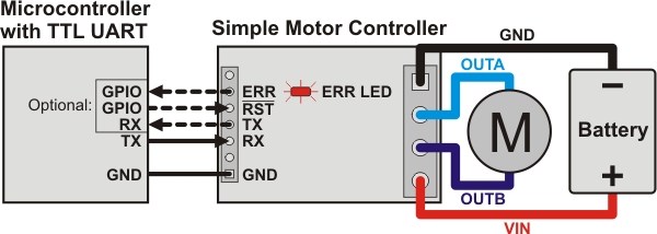
@Technopro Why would you want to, even if you could?... I am still confused at why and what you are trying to do... The EZ3 has 3 pins, right?... 1) ground, 2) +5V power, and 3) the signal pin.... It's the signal pin that sends the PWM to the H-Bridge to make the motors move... You do not put any power down the signal pin... As I said the EZB outputs PWM on that pin to the H-Bridge. The +5v pin would power things like sensors, servos or any other 5V device..... and of course the ground is the - side of things... Take a look at the picture below... No the same as an H-bridge, but you should get the idea of how a motor controller works...
Ez-b v4 doesn't have regulAted ports so the voltage is what ever voltage you putting into the ez-b. do I have to buy regulators to regulate the signal voltage or is the signal regulated? Can I have a 12v battery up to the ez-b and be able to wire the hbridge the same as usual? No regulators or anything extra?
Yes, but that is the + power pin, not the signal pin... Remember, 3 pins.... On the EZB4 there is no +5 regulated power pin... Now it is whatever voltage you are using to power the V4 board with... The signal pin is the same on both boards and virtually all other microcontrollers as well... It's the signal pin (outer pin on V3 and V4 of the EZB board) that controls the H-bridge...The centre pin is +5 (on the EZ3 and whatever on the EZ4) and the inside pin is the ground pin... Makes sense? Take a look at my above post at a diagram of a simple motor controller... The EZB just sends signals to control the motors (via the H-bridge)..It doesn't do any of the hard work.. The motors, H-bridge and battery do all the work...
What is it you are trying to achieve or figure out? Please explain your question more clearly. However, I shall try to cover all bases here, again.
The EZ-B V4 Signal pins are 5v if you measure them with a multimeter and they are set to on or PWM at 100%. A digital on or high will set the signal pin to +5V, a digital off or low will set the signal pin to ground.
Which H-Bridge do you plan on using? Most (if not all) do require a 5V supply, this can be taken from the VCC pin on any port (V3 only) or from a 5V regulated supply from the battery. If using the V4 you will need to either supply the EZ-B with 5V or you will need to regulate a battery to 5V and power it from there.
The whole "no regulator" thing only applies to the VCC of each port on the V4.
The signals from EZ-B V3 or V4 to the H-Bridge In1 to In4 need nothing extra added. The signals from EZ-B V3 or V4 to the EnA and EnB (or PWMs) need nothing extra added. Any VCC from the EZ-B V4 to the H-Bridge +5v will need to be regulated.
Edit, a bit more info @rryerson you are slightly incorrect or haven't quite understood everything correctly (not a complaint at all, we all learn). The Signal does send power to the H-Bridge but it is very low current.
If digital is set to off it sets the signal to ground. If signal is set to on it sets the signal to +5v. If the signal is PWM to 100% it sets the signal to +5v. If the signal is PWM to a lower percentage it simulates a lower voltage, i.e. PWM of 50% would simulate 2.5v, PWM of 80% would simulate 4v, PWM of 20% would simulate 1v.
The In1 to In4 of the H-Bridge (sometimes called Ain1, Ain2, Bin1 and Bin2) use this high/low or +5v/ground to determine what to do. The Ena and Enb (or PWMa and PWMb) sense the speed required through PWM.
@Rich... no worries, I know the signal has current behind it... My fault, I didn't elaborate well... I was trying to get Technopro to understand the basics (wanted to keep it as simple as possible) of a motor controller and what it does... I know he is headed for a light bulb moment any second now... LOL