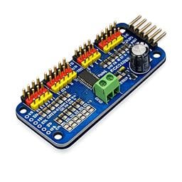






When you hook the motor controller to the ez-b, what is the max voltage that can run on those connections of the motor controller. Do I need to regulate it or can I keep 12v through the ez-b on it?
Asked
— Edited
 Resolved by Rich!
3 Participants
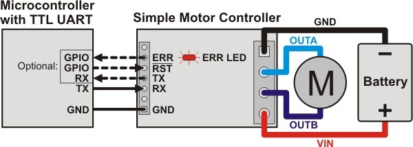
Thanks guys. I guess it was sort of a confusing question. The signal is 5v. I thought it was the same as the battery. I'm planning on using the l298n. So theres one screw jack that needs 5v VCC?
The VCC on the digital ports is whatever the input voltage is. The input voltage basically just passes through to the VCC of each digital port.
Each signal is 5v tolerant. This means each signal will read +5v when set to high or on. There will be very little current for these, just like on the V3.
You are correct, the terminal labelled 5v requires 5v. Again, check my tutorial, I included clear photos of the connections and these indicate that there is a +5v from EZ-B to +5v on the L298n, you will also be required to provide the power supply to run the motors, all others (excluding ground) are from Signal pins.
Don't worry, I know how to wire an hbridge. So I would need to regulate the vcc from the ez-b to 5v and wire it into that port. Ok, I think I'm all cleared up. Thanks.
No problem. As always, just ask if you need to but I will attempt to make you work (at least a little) for the answer