
PRO
jstarne1
USA
Asked
— Edited
http://makezine.com/connected-home-project-contest/
I am entering and so should you! Show off your ez robot home innovation idea / Project . Though I would like to win I would like even more if some some stiff competition in the EZ Robot community took the cake. $500 bucks is a lot of goodies to play with this summer.
If you are going to submit your project for the contest let us all know here and see you at the finish line!
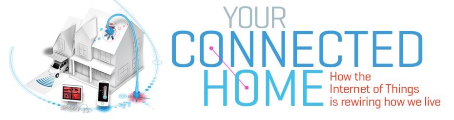
By best, I mean best documented, most innovative, and most original project. The winner, to be picked by a panel of MAKE editors, will have his or her project featured on makezine.com and will receive a $500 voucher from the Maker Shed. There's also a special bonus prize.
The submission period is open now and ends at 11:59 p.m. PT Feb. 6 so get started now! Full details and official contest rules can be found here.
This is an awesome contest to showcase your skills and creativity with the EZ-B! Good luck!
I grew up having a fishtank in every home my parents lived, there were different varieties and they were all
wonderful. Many people would like to have a nice fish tank but shy away because of the complexity and expense.
With my project the maintenance of a Salt water marine habitat is much easier. The controller can do anything you
can imagine but for know I will tell you how you can setup relatively cheap and automated solution to have a
beautiful interactive marine display. First you have your basics and can purchase a tank kit from a store with the
needed salt solution to mix with water these can vary on your brand. Get yourself a Aquarium stand with cabinet
below the aquarium so we have plenty of space for automated goodness!
The setup i will show you will switch on and off three sets of lights and different ties of the day, simulate ocean
alternating currents and even storms. Turn on or off pumps and wave makers. I really love the changing color. In the
morning i start at a 18000k purple, then 10000k blue, and a 6000k daylight bulb to simulate noon, after that the
process reverses just like in nature producing a simple yet spectacular change of colors as your day goes by!
The basic items needed
Filter portion from hardware supplier-
5 canister filters PVC for potable water 3/4" input and outlets
5 brackets for mounts
7 male mal pvc threaded connectors
3/4" pvc hose 12 foot
Mag 7 3/4" pump for water fountains and ponds ( 5 year warranty is awesome)
12 ft 1 inch pvc pipe for plumping
1 can pvc glue for potable water
Electronics section items
1- Ez Robot Microcontroller with bluetooth
2- download free software ARC ez robot.com
3- Purchase Automotive style standard 30 amp 12 volt relays SPDT - 5 ( i have 7 for expansion)
4-Spool of 14-18 guage two color wire RED / BLK
5 Spool of blue wire
6- 7 servo ext cables red/wht/blk
7-100pc box of femal spade connectors
8- Crimp connect tool
9- 5 different colors electrical tape, usually found in 5 pack assortment
10- a old computer case or server case like i has with PC power supply
11-a pc with windows 7
12- 60-40 lead/silter solder
13- 30 watt soldering iron
15 - 5- Darlington Switching Transistors
16- 5 - 1/4 watt 1k ohm resister
17- 5-60v 1 amp diodes
18- 6-12 volt toggle or rocker switches switches
misc machine screws and matching bolts to hold your repays in place or you can opt for super glue
about 4-6 hours of time and patience
First, you need a case to put all your electronics in
Pic 1
I had a Sun micro computer case with old 200 watt power supply. Its more than enough to power our Ez robot
controller and 12 volt relays.
Step 2 Convert your PC power supply to a regular bench supply, be sure its not plugged into the wall and has been
sitting overnight to make sure capacitors are empty . Safety First!
To do this you need to cut the Molex 40 pin connector off, there is only one green wire. there are several black
wires, bundle them together , strip the ends and solder all the black grounds together and the one green wire. A zip
tie works great at holding the numerous grounds together to solder. Vuala!
- Now you have a regulated power supply - next find your 5 volt + wire , it will be solid red seperate it fro the
side and seperate one of the yellow wires. there are several dont worry
all the excess wire not needed and ziptie it. I myself Cut it away once teh project was finished as we only need
+5 volt wire
+12 volt wire
green power on
Black ground wires
Congratulations thats your power supply and case are now ready.
Second Step is mounting your Relays, i mounted 7 in line and drilled holes just to hold them in place with machine
screws. if you dont have a drill just use some super glue. These are standard 30 A 12 volt relays
2nd picture, mounting the relays
line them up neetly
3rd mounting position ezb
mount the EZb controller off to the side by itself, the space looks empty but it will fill up quick
4th picture wire the 5 volt toggle switches
Drill one hole for wach switch, try lining them up and I used a 1/2 dril bit , insert teh switches and tighten them
down.
wire to one input and you an daisychain the same pins on all the switches to make this each, cutting peices of 4
inch wire red ( for 5 volts) and Crimp a spade connector on each one, do so for all 5
5th picture front of switches mounted
These are manual override switches in case your computer crashes , power goes out ect.
7th picture line of relays mounted
Each of the relays uses 4 pins. they look complicated but its OK your just wiring two pins at a time.
are to trigger the relay coil switching it into " ON" position , the other 2 are the "pass through" connection we
will use to control our household aquarium appliances.
7th line of relays mounted
Now We want to make the brains of the operation. A switching transistor board. It sounds more complicated than it
is. The transisters are called Darlington after their designer. They have three legs. One leg is just ground, then
one is the collector and emitter. When the transister recieves a "on signal" from the Ez Board then it makes a
connection to the relay closing the loop to power it. Here is the diagram. remember just three legs, resistor is IN
LINE with the signal fro the controller and one is just the ground as depicted here.
8th picture, Darlington tip 120 transistor
Here are the three parts you need to make each circuit that turn on and off our relays that turn on and off our
appliances. See how these to are linked yet? you will
9th picture tip 120 resistor and diode
I use a piece of perboard from radioshack and stick the legs through and bend them to hold them in place.
10th picture darlington mounted on perf board using 4 1" standoffs from Radio shack and a drop of superglue on the
tip of each.
11th picture barrier strip mounted somewhere in open space for future 110 V supply
This barrier strip will later be the source of the 110 volt supply to go to each relay so it can power things like
pumps , lighting , wavemakers ect. Here is used a bit of double sided tape.
12th female crimp connects
Here is a box of female crimp connects, buy 100 so you have plenty for oops moments, you will use this for all
connections from the transistors to the relay coils.
13th picture multicolor tape
Pick up multicolor tape. NOTE USE WHITE for 110v white hot ( this is for safety)
14th Picture - Top of controller so far , not too bad right, this is about half way. You are almost there !
15th Picture darlingtons wired
Wire the resistor inline with the signal wire like shown , ground to ground and emitter will go to the relay. Use a
solder iron and 60-40 solder, touch the iron to the leg first then touch the solder to it at the same time and
solder will flow over the connection like mercury
It should look like this once done
16th picture topview , transistors wired
Next the third leg that goes to the relay like in the diagram and pics I showed you. Give yourself some slack and
use blue wire so that it is cleary different that any of our power wire colors we are using. Agian safety first. On
the end of this wire we crimp the female spade crimp connector and goes to the Ground side of the SPDT relay coil .
Repeat this neatly for all 5 in a row
Next you will apply 12 volt power wires to the positive pin on the relays. and collect all of them to a yelloy wire
from the PC power supply. Repeat for all 5 sing crimp connect ends. TA DA! there you go, you have power to your
relays to start switching.
18th picture blue wires on crimp connects to relays
Going back to those front panel switches we did , you will need to get some wire perhaps green and run one end from
each front panel switch you installed to the input of each transistor. solder it down on the transistor side and use
a femal crimp connect on the toggle switch side. repeat these steps 5 times.
Now you have 5 relays wired up and if the power were plugged in your Power supply when you flip the switches you
will hear the relays click as they turn on or off. That is the sound of Progress my friend. Almost there with about
a hour left.
Use the barrier strip to run a single power wire that will plug into your wall outlet. you will divide the barrier
into three sections and you really should use a marker to mark them. Line/ WHITE 110V , Black Nuetral 110V and
Green Ground 110v. Never leave a white 110 volt wire exposed, you will want to wrap any connections very well with
electrical tape matching their associated colors.
18th picture blue wires on crimp connects to relays
Each wire here on this strip will use a spade fork connector. , on one pin of your pass through you feed your live
wire and use crimp connect to go to your relay, the left available pin will be the one that actually connects to
each line wire of the 110v appliance you want to control. Repeat this 5 times and cover all connections and mark
them clearly.
20th picture clearly marked 110 volt power
21st picture relays color coded for future maintenance
With each connection mark every wire with color code so it is easy to troubleshoot in the future if you ever have a
relay go bad. I have never had one go but it will happen eventually because it is a moving part. They will last you
years though
22nd topview of the controller showing the position of the wires for appliances
I used red and black wire i had to run to each appliance power. You can use standard lamp cord as long as there is a
polarized strip on one side to indicate the LIVE wire side. All teh netrals are attached to the nuetral side of the
barrier strip. The relays only trigger the live wire side and the 110 volt item becomes energized.
I have three lights their own power and 2 wave makers and room to add a UV sterilizer in the future.
Now you should be able to test your controller, plug the power into the psu and teh fan will come on, then plug in
teh 110 v barrier strip source power. Flip a switch and each applie will become powered on. repeat for every
switch.
Lastly it comes time to plug in the micro controller once the whole setup is wired. in order apply each white signal
wire plug just like in all the pics to teh servo plugs on the EZ board. Signal pin which is white faces outward.
Start at D0 , then D1 , D2 , D3 , D4 . These are the digital ports that will toggle the relays on ans off using
those transistors we installed earlier. You will need to use barrel connector adapter included with EZb , connect
the 12v yellow supply to the positive sode of the barrel adapter and tighten the screw down then do so with ground
as well to the ground on the PSU. You will see a pretty blue light, TA DA!
Almost done
Now for your PC - INstall a usb bluetooth adapter and ensure you are using the stock bluetooth Microsoft stack in
the porperties of the device.
Go to EZ-Robot.com and intall the EZ - Builder software
Once you open ex builder open the Controls tab, and tehn Digital pin control. Open 5 of them and label each with the
appliance. Mine are as follows
Blue 12000 K actinic light
Purple 18000K light
Daylight Bulb Light
Left Wavemaker
Right wavemaker
Once you do this it pays to save your project in the upper left hand corner. select save and name your project "
Smart Fishtank"
Open a EZ Script box and you can copy and past a preset script. Setting time is easy for each line. for example
(D0,ON) 08:00 , that will turn it on at 8 am. simple right? just like setting your sprinklers. Here is a example
script but you can change the times and there are easy to use instructions by clicking the question mark in teh top
right hand box as well.
Code:
waituntiltime(08,00)
set(D1,on)
waituntiltime(10,00)
set(D2,on)
waituntiltime(18,00)
set(D2,off)
waituntiltime(20,00)
set(D1,off)
waituntiltime(20,00)
set(D3,on)
waituntiltime(08,00)
set(D3,off)
you may modify this to your liking and you can even due so on a wyme. Once you have this in , click connect and
select COM 3 , the red flashing light on the EZ board will turn solid and so will the blue light . Continuous
blinking means it is not connected yet.
Test this cycle for 24 hours and you know everything is working perfect, ou can use more relays to automate more
functions. You can even use this same priciple to control your home lighting! EZB supports voice control so you can
set the lights to all turn off with your voice : GOODNIGHT FISH: or wake them up : goodmorning fish!:
When you buy a EZ robot kit it already comes with a nifty 2.4 ghz wireless camera you can use to mount on the edge
of your tank. through the buety of remote desktop you could enjoy your aqaurium from anywhere. I set my background
on my phone to update every 5 minutes with a new picture from the EZ camera. Now the Board uses the PC connection
to do all these things which is what make is stand out from things like arduino!
Here are some video links to the tests and demonstrations, I hope you enoyed this build and I hope you add more
features now that you see how easy it is.
If I had more time I would have covered the EZ-B powered stair lighting I have designed but I found out about it at around 6pm (GMT) yesterday and was out in the evening too so had all of about 2 hours to knock something up. Maybe next time I'll be in a better position to submit a kickass EZ-B based project.
Hopefully it's what they are looking for. They only allowed me to upload one pic so i labeled each Are where I would have inserted a pic that is already on ez-robot . I inserted URL for three videos doing the demonstration with ARC. I didn't have time to do a custom video just for the contest though.
@Josh .....dream a little and tell us what you might do with 500 USD! ....Malwarebytes has saved my butt a few times as well, glad it all worked out
http://makezine.com/blog/
http://makezine.com/2014/02/07/connected-home-contest-we-have-a-winner/
A nutrition monitor for the elderly. They said notable interesting projects will still be featured as running ups but no prize.
The concept? - So granny is suppose to enter her BMI, and remember that she needs to eat and also remember that she needs to put her food and drink in containers to be weighed before she eats them so the little snitch machine doesn't twitter that she didn't weigh her food? Not that it knows that she actually ate anything or that the food was healthy. It's not monitoring nutrition as the project name suggests, it's just a (what I'm going to assume) is a fairly inaccurate weight gage with a twitter posting feature.
I think it would have made an awesome jr. High science fair project. But come on Make magazine. At least you could say that goofy solar plant from last year was cute.
Make magazine should have said "Contest - please enter if you want to make something with parts we already hoc, and your device will be overly simple and not practical, so we can package up another Maker Kit"