Asked — Edited

Look What I Got

Hello everyone!

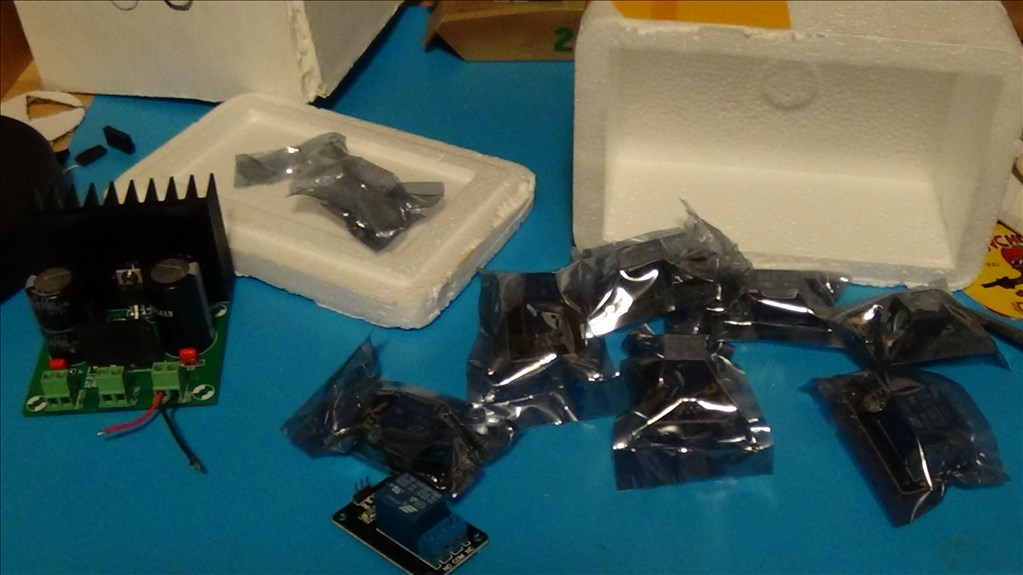
I just got my first shipment of parts from china which included: 8x relays User-inserted image

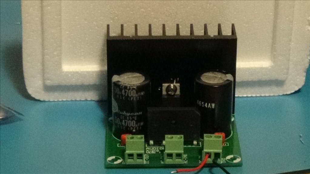
and 1x 5amp adjusting power adapter(Audiowind). User-inserted image

Just waiting for some regulators, and I should be good to finish some robots!

A question: Relay wiring?

Relay: User-inserted image

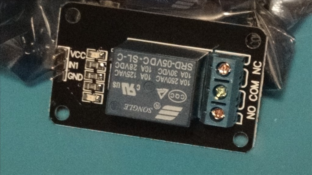
How do I wire this up?

Thanks, Tech


ARC Pro

Upgrade to ARC Pro

Your robot can be more than a simple automated machine with the power of ARC Pro!

United Kingdom
#1  

No is normally open, meaning when the relay isn't energised the contact between com and no is open. Nc is normally closed, the opposite to normally open. Com is common, this is what gets passed through to No or Nc.

Vcc is likely your +5V Ground is ground In1 is the enable for the relay, setting high will switch the relay making No close and Nc open.

Was there no datasheet?

#2  

on the ezb VCC=red (it may be ok to use higher than +5v, just a guess though), ground = black and in1=white (signal)...

e.g. Set(D0,ON) engages the relay on pin D0... you want your switch between NO AND Com on the relay itself... when Pin 0 goes high the relay closes completing your circuit...

PRO
Synthiam
#3  

does that have a transistor on the board? I don't think you should be connecting it directly to the ezb without a transistor. Also a diode is necessary on relays because when the relay closes, the voltage is reversed and pushed into the circuit.

PRO
Canada
#4  

Lol I was thinking the same thing as @DJ that board may use an LED as a flyback diode but it doesn't look like there is a driving transistor there to handle the current needed by the relay (unless it's surface mounted under the relay or on the other side of the board)

United Kingdom
#5  

I assumed these would have the switching transistor circuit built in to them but perhaps not. @Techno, post either a link to the part or the datasheet on it. Also a picture of the other side would be useful.

#6  

Good point... I never thought to ask as I have some that look very similar... They run on 5V and draw about 20ma so I am able to connect them directly to the ezb @Tech do you have the stats on the relay board?

#8  

@Tech... Just looked at the stats... You can safely drive this relay right from an ezb digital port...

Quote:

EBay Description:

5V 1-Channel Relay interface board, and each one needs 15-20mA Driver Current

United Kingdom
#9  

That datasheet is for just the relay which is on the board not the board itself.

It looks like, as Richard said, you can drive it direct from the EZ-B (as per my first reply) however check to make sure it does have the driving transistor and diode otherwise there is a risk of damaging the board, the EZ-B and the battery.

If in doubt, add a driver circuit. This would be the TIP122 circuit with the optional diode.

Or if you are feeling brave and want to risk the warranty on the EZ-B you could just try it and see what happens however I don't recommend that option personally :)

#10  

If you really want to be sure you could always test it with a multimeter first to see how much current (at 5V) the relay uses to close...

United Kingdom
#11  

@Richard, with no diode there is a chance of back feed from inductive loads. You don't want back feed into a LiPo battery... You don't want back feed anywhere to be honest :)

#12  

Any which way, I have a couple of transistors(don't ask where I got them from) that are 2n2222 transistors. 2n2222

Will these work? Added picture of pin layout

User-inserted image

#13  

@Rich, I guess I didn't even realize it or even thought about it as have only been using niMh batteries in most of my projects... Still, good to know... Thanks...

#14  

Will those transistors I mentioned in my last post work?

#15  

I know I've arrived late in the game but I purchased several of the 5 volt relays for use with one of the Roomba projects (not completed yet) but I did post some info about them a few months back. One key reason for my selection was that the relay boards are optically isolated from the EZB or any microcontroller for that matter. Also on ebay: http://www.ebay.com/itm/5V-1-Channel-Relay-Module-H-L-Level-Triger-with-Optocoupler-for-Arduino-Raspberr-/221407959915?pt=LH_DefaultDomain_0&hash=item338cf15b6b

User-inserted image

PRO
Canada
#16  

@TechnoPro Just wanted to chime in that a 2N2222 is perfect for this application, and a 1N4148 or 1N4001 should work for a fly back diode.

#17  

Thanks Jere! ...How would I wire it up...?

Robotdoc, are you saying that my relay is fine by itself? Or is that just for what you have linked?

#18  

Technopro - No the link is for the optical isolated relay. The ones you have evidently are not power isolated.

#19  

Ok, well if I happen to buy more relays I'll go with those! Thanks Doc.

#20  

Jeremie, are you sure of the 1n4001's? I read they are forward voltage vf 1.1v.

PRO
Canada
#21  

Hi TechnoPro,

Most of the examples online use a 1N4001 or it's higher voltage cousin the 1N4007. Forward voltage doesn't really matter in this case as the diode is just being used in a flyback configuration which means that it is dissipating the energy left in the coil once the transistor stops conducting, efficient forward voltage doesn't really matter in this case.

Here's a schematic for interfacing directly to a relay from the ez-b:

User-inserted image

While I am pretty sure that 3.3VDC will work with a 5V relay, if it doesn't then use 5V instead of 3.3V and increase the resistor to a 2.2kohm