
Lcd Display Help
Hey guys.
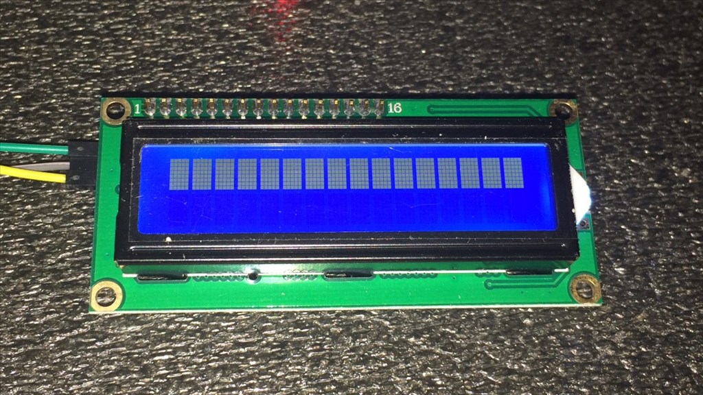
I'm having a little trouble with an LCD display I recently purchased. I have read through some of the posts on the forum to help me get this going, but I need a little more help. I have it connected to D12 going through a 5v regulator. Ground to ground, Vcc to Vcc, and SDA (which I believe to be RX) to a signal pin. It lights up but when I try SendSerial(d12, 9600, "Hello" ) nothing happens. I have also tried a different port and changed baud rates, no change.
Now I believe this is a serial (what I was after) and i2c compatable so it should work. I havn't found a data sheet for it yet but here's a link to it, if it helps. Any ideas what's going wrong, or even if this thing is compatable with the v4? I hope some one can help as I would love to get this working.
Thanks in advance.

Ah the good old LCD display and serial commands.
This is what helped me understand how frustrating datasheets can be!
While it uses I2C rather than serial, this topic should help you.
It's not as simple as sending text for it to appear. You need to let it know you are sending text, you need to set cursor positions etc.
I'm sure I have a 1602 backpack on an LCD somewhere which I have covered, and I am sure the commands were either the same or very similar to those in the topic I linked to (just replace the I2CWrite for the SendSerial command).
Here is another topic worth reading through.
Try these commands, I can't guarantee they will work but I just found the list
And possibly try this script;
Haha, those were the exact two threads I was referring to. I'll give the script above a try and report back in a bit.
@Rich.
Tried the script, but it comes up with an error...
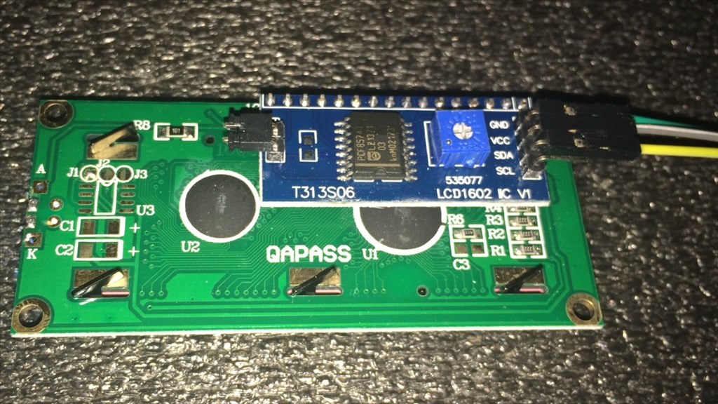
Are you sure that's a uart/serial lcd? The ports read i2c labels...
If it's i2c, like the labels display... You're in for a treat. Those cheap screens have zero documentation and to my knowledge, no one has gotten one to work yet
My one is both serial and I2C (there is a jumper on it to change it) however I am unsure if that was the Digole or the cheapo one, I'll check when I am home, I have a feeling DJ is correct and I threw the "El Cheapo 1602" in the bin as it was useless.
I'll check in about an hour, just need to get home and check it out.
Edit: No need to wait, I found my topic I made... here. The one I threw out was the "El Cheapo 1602" as no commands were known nor could I find any reference to them.
Don't immediately throw it out, I'll see what I can dig up on it and decipher.
No problem. Sounds like I have been bitten by the "wrong description" bug then. I did contact the seller to confirm if it was both i2c and serial, which they did. Oh well. Thanks guys.
@Steve, this may not be relevant at all (especially if your LCD is I2C and not serial) but try putting non number commands in quotes as below... It should get rid of the missing sting quote error at least...