The boards have been pretty quiet so I thought I would share what I am working on now.
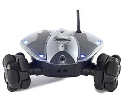
This is for robots using an on-board computer I have started making a plugin that is designed to use the xv-11 sensor, wheel radius and encoder counts per revolution of the wheels to make a map of the environment. It also uses the compass part of the 4-in-1 sensor sold on this site.
The map is currently stored in a SQLLite3 database. It is housed in the plugin directory. I don't know if this will be the final design or not but it is what I have working right now. There is a map table that is created by the user with the plugin. It contains the X coord, Y coord, tile and Counter fields. This will be used to store the map as it is being updated. The tile will be marked when the LIDAR recognizes something in that location of a certain intensity.
Quote:
The tile size is determined by the wheel diameter. If you have small wheels, you have small tiles. If you have large wheels, you have large tiles. The current environment that I am testing in has tiles that are about 4.19 inches by 4.19 inches. This is because I have wheels that are 4 inches in diameter and if you take the wheel diameter * pi / 3, you come up with 4.188790266.... I round this to 2 decimal places. If you had wheels that were 2 inches in diameter, you would have tiles that are 2.09 inches. If you had wheels that were 12 inches in diameter, the tiles would be 12.57 inches. The logic is that the wheels would be much smaller for robots in smaller environments and much larger for robots in larger environments. Larger wheels means faster moving robots and thus the updating of the environment would have to account for faster moving robots. The number of tiles in the map is determined by the configuration screen by setting the size you want your map to be. In the test, the map is 50 feet x 50 feet. Using a robot with 12 inch diameter wheels indoors in a 50x50 foot house could become problematic. These are all subject to change depending on testing.
Well the information quoted above has changed. I am in the US and as such am more comfortable using inches and feet, so I am making 1 inch tiles for everything. The wheel diameter is still important but not as important in laying out the grid. I am converting the mm readings from the LIDAR to inches and marking the squares. We will see how this works out and go from there. This, along with everything else is subject to change as I go through it all.
The map on the screen is loaded from the SQLLite3 database initially. As things are seen by the LIDAR, the map table is updated and the display is updated by marking the corresponding tile on the map.
Eventually my goal is to take this logic and use it in SLAM. I plan on starting with some simple SLAM using the RANSAC algorithm which is best used in indoor environments. This is because it estimates and creates landmarks based on straight lines. From there I will use the Extended Kalman Filter for data association. This allows the robot to recognize landmarks and then adjust its current position on the map based on these landmarks.
One of the reasons that I want to store this information in a SQLLite3 database is that this would allow me to have multiple maps housed in different tables. The configuration screen could be modified to allow the user to specify which environment the robot is in (office 1, Office 2, home, Mom's house for example). These maps would be stored in different tables and the user would just switch to the map that pertains to the current environment. Another thing that these multiple maps could be used for is to handle different floors of an office building, one for each floor.
The test map is about 13 meg in size. This isn't too large but is only based on a 50x50 foot house on a robot with 4 inch diameter wheels. If you were in a warehouse or large office building with a robot with small wheels, the size of the database could get really large I would imagine. The goal is to get this to work in a smaller environment, and then see what needs to be done to handle larger environments.
Eventually, I plan on incorporating a path finding algorithm. This shouldn't be too hard to do because it is done in video games like crazy. There is plenty of sample code to build from.
Anyway, that is what I am working on currently. I suspect it will take some time before I have something to share. This is a pretty ambitious project and I will post updates as I accomplish different things with it.
I am not sure if I will sell this plugin or make it freely available. This is something that I will decide after I know how it works in multiple environments. If it turns out to be simply amazing, I might sell it. If it just works, I will give it away for free and continue working on a final solution.

Hmm, interesting read. So, from what I gather, the compass part won't even come close to telling me if a turn is complete (5 degree variance from start to finish of a turn for example.)
I hope Jeremy isn't too busy with other things to address it right now.
The way it sits now the compass is unusable... I have two 4 in 1 sensors that I can't currently use...
Just saw in another thread that the current 4in1 is only available from Brookstone, and they are re-designing a Rev 2 board at this time. I hope that isn't going to be required to get the compass to work, but it does mean you may be waiting a while before you get the one you ordered (and without trying to be mean, EZ has never met an expected ship date on new product yet, so I wouldn't hold my breath too much).
The thread I linked to has information on how to get a 3rd party sensor working correctly with EZ-B. You might want to go that route if you are in a hurry.
Alan
Thanks Alan,
I am going to focus on getting the encoder issue (too many counts with 2 motors of my config with a Kangaroo) going first I think. This is where I am with SLAM right now anyway, so it is important to get this resolved. It may be possible not to use the compass and will probably make me code the other stuff better anyway
If I come to a time that I need it, I will either make a subsystem for it or get the 4-in-1 v2 when it is available.
I am also in the same disappointing situation. None of the compass values are consistent or of reference value. Has anyone been able to use the data, or get it to work? Seems like a wasted function. I bought it thinking it would give me a zero to 360 reference. Got nothing.
Ron R
I got side tracked some from this by making the circuit boards for the logic divide by 2 circuits that I needed for my motor encoder/motor combo. I had planned on getting back to this right after getting the prototypes completed for these, but that didn't happen.
My brain was on circuit board design and I found it really hard to get my brain off of that. The cost of the first 64 of these little logic divider boards would be really high for me if all I did was produce the 2 that I needed for my prototype, so I toyed with the idea of selling the others to recover the cost. I gave it some thought and decided that I needed to build a subsystem controller board anyway, so I could just include these two logic divide by 2 circuits on this same board, thus making the cost go away for them. I had a far less difficult time convincing myself that the cost for these subsystem controller boards was out of line when there are a lot of benefits to doing this in a robot. The good news is that there was enough room on the board to include 13 additional digital divide by 2 circuits per board meaning that I will still be able to recover the cost to produce the Subsystem controller boards if I sell these. There will be a total of 52 of these logic /2 circuits up for sale with the first order.
I mention this just because it changes, quite drastically how the robot is wired. This will take some time to get the boards, and then to build them, and then to rewire the robot to use these boards. This is all good as in the long run it will be a much cleaner robot inside. It does mean that I lost my test platform for working on the navigation part. I estimate that it will be a couple of weeks before I have everything assembled again to a point that I can work on navigation.
Hey David, I now you are working to get this working, I was wounding if you seen this video...https://www.bing.com/videos/search?q=lidar-vx+11+windows&&view=detail&mid=AC1AF37427DC4D4B7403AC1AF37427DC4D4B7403&FORM=VRDGAR
This guy does not seem to reply publicly but maybe you could ping him off line to see if you can get ay tips to complete this awesome app.
Thanks
Really the only tips I need right now is time. I have all of the parts working. Just have to have time to focus on it.