Asked — Edited

Instructable - 0 -24 Volt Adjustable Power Supply How To :)

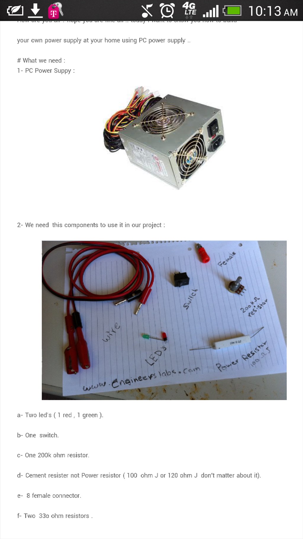
Hello guys this is a improment over the past tutorial posted for converting a PC power supply to be a bench 12 volt supply. This tutorial uses the same computer PSU to make a adjustable 0 to 24 volts. This means testing equipment of different voltages will be much easier. Now you don't need to hunt down a ad adapter and cut it up only to find it's not really the voltage you needed. User-inserted image

ARC Pro

Upgrade to ARC Pro

ARC Pro is more than a tool; it's a creative playground for robot enthusiasts, where you can turn your wildest ideas into reality.

#7  

you could place a small voltmeter in PAR and an ampmeter in series and watch the voltage or the amps as you adjust the pot.

#8  

http://www.youtube.com/watch?v=OJX4h80uw88#t=120

Here is the YouTube video for the author. Hopefully you found this useful I plan to make one of these myself as it would be very useful.

#9  

http://engineerslabs.com/2011/10/make-a-power-supply-at-your-home-0-to-24-volts/

Here is the original tutorial but I wanted to post it because you never know if the link will go dead

#10  

Thanks Mel I was going to suggest that! That's what I believe I will do with mine so I can avoid using a meter

PRO
New Zealand
#11  

Here's one I've purchased that gives me most of what I need at this stage... check it out!

It uses the ATX supply and routes the -12, 3.3, 5 and 12 volt ATX outputs to screw terminals, each protected by a 1.25 amp resettable polyfuse.

dangerousprototypes.com/docs/ATX_Breakout_Board

#12  

Hi. Where the ceramic resistor goes. I'm confused goes to the 24 v outlets or to any red and black wire?. Got stuck here Thanks for any help

PRO
New Zealand
#13  

I never used it... apparently it was an optional extra.

Worked fine for me without it.

#14  

Looks like it goes between the + and- wires coming from the pot. Red and black lines in the picture.

PRO
New Zealand
#15  

According to their site Dave the load resister was needed in some supplies to start the unit... not needed in most supplied but included as an extra. Nice of them in my opinion.

"A 9 Watt load resistor is included but not soldered to the board. In our experience most modern ATX supplies don't require a significant load on the 5 volt rail to start. An artificial load just wastes electricity and creates unnecessary heat. Please let us know your experience."

#16  

Ahh, right. I forgot some older ATX power supplies need load to start up. I actually have one sitting on my workbench shelf I sometimes use for bench testing. I needed to hook up an old 3.5" floppy drive to get it to run. LOL. ;)

#17  

I just jump the green and black wire to power on my old PC power supplies... User-inserted image

#18  

Sweet trick RR. I remember years ago reading about this jumper method. Back then I never really understood what wires to jumper. This is a lot better then having a big 3.5 floppy drive strapped to the top of my old ATX like a big humpback. LOL. Thanks. ;)

PRO
New Zealand
#19  

I have mine installed on the wall in the workshop... gives me some helpful access when I need it! User-inserted image