Australia
Asked — Edited

Inmoov Robot, How With Ez-B Robot Controller., ?

Hello Ezrobot Community, All,

I'm wanting to test InMoov Robot using EzRobot but very unsure of what parts I need to get in the shop, are you able to assist please?

  1. Do I get the whole EZ-B development kit? or just the wifi robot controller is enough? but then I already have a 6V output battery pack, will this be sufficient to power up the EZ-B robot controller and the 5V servos (which I currently use..)? or I need to get the battery in the shop?

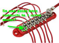
  2. Do I need the inline 5V regulator? (my servos runs at 5 volts)

  3. If I can use my 6V output battery pack, do I need to get the alternate power adapter? (from the shop)

I just want to do basic test in controlling my servos with EZ-B.., testing min and max turning angles of the motors,

Thank you for your assist,

Kind Regards, Roger


ARC Pro

Upgrade to ARC Pro

Unleash your creativity with the power of easy robot programming using Synthiam ARC Pro

#1  

Hi Rodger, I'm just starting my switch-over to EZ from MRL. In my case, I just purchased the EZBv4 controller as I already had most of the servos that I needed and a camera. If you can use the other parts in the kit, it's a good deal. As for the battery pack, as long as it can provide enough amps for you servos it should be fine, but you should use a 5v regulator if that is the max voltage for your servos. Good luck with your build!

Dan

#2  

You can start off with the EZ controller and the camera. You can get by a long time with those then add to it later. Get an extra power adapter. You can run your 5V servos with any power source. Sounds like you will have to convert down from your battery.

Get a bunch of servo extension leads as well. Got mine from Amazon in bulk.

Australia
#3  

Hello :)

Thank you for your help, ok I have ordered the EZ controller + camera pack,

  1. https://synthiam.com/Shop/AccessoriesDetails.aspx?productNumber=9 (is this the power adapter you are talking about?)

  2. I use the https://www.ebay.com/itm/New-6V-Power-Supply-300W-6V-50A-Switching-Power-Supply-WITH-CE/173071100075?hash=item284bd768ab:g:dJ4AAOxyXHpSTJZ- battery suggested from Gael in his website. , when you mentioned "convert down from battery), does that mean I need to get the "Inline 5V regulator" as well for the InMoov servos?

Thank you for help,

Kind Regards, Roger

#4  

Hi Roger,

  1. Yes, one of those should come with your EZB/camera. I bought 2 more when I added other controllers.
  2. You say that you have 5V servos and that is a 6V power supply so you will have to drop that voltage somehow. You will need to get a converter that can handle that amperage. Or get a 5V power supply. The EZR will run on either. I would not get a bunch of inline converters due to cost.
United Kingdom
#5  

Roger,

What 5v Servos are you using? most servos have a working tolerance of +/- a couple of volts so 6v battery may be OK?

Have you looked up the Spec of your Servos?

Australia
#6  

Hi Perry, Cem,

Thank you for your help to my questions, really appreciated, I'm still beginner on this and learning as I go, your reply is very helpful. Also very agree on the inline regulators are costly,

Hi Cem, All,

The common servos I'm using is following Gael's hardware + bom page, You got the point, I checked their voltage as below:

  1. HK15298B , HK15298 - Voltage: 4.8v~7.4v
  2. HS805BB - Voltage: 4.8v~6v
  3. PDI-HV2060MG jx - Voltage: 6~7.4V
  4. Towerpro SG91 - voltage: 4.8v (only runs at this voltage, a small servo for the eyes)

Is my 6v power supply going to be ok to run these?

I'm worried about the small SG91 servo, since it only runs at 4.8v, so does that also mean I must get a 5V power supply as well in this case?

Thank you very much,

Kind Regards, Roger

Canada
#7  

I run all my servos and the small eye servos @ 6v with no problems.

Australia
#8  

I'm sorry, I done a typo,

For the eye servos, I use:

Model: DS929HV Operating Voltage: 6.0V / 7.4V

Hi 3dPrinterGuy,

So you run all the servos (suggested in Gael's hardware + bom page) with no issues @6V)? is that what you mean?

Thank you!

Kind Regards, Roger

United Kingdom
#9  

@ Roger, All these Servos we work fine on 6v.

Australia
#10  

@Cem,

Thank you for your confirmation! I'm very excited!

Australia
#11  

Hello Everyone, All,

I have another question on following Gael's tutorial, the ribbon cables are being used to say connect the servo motor to the arm breakout board and then to the nervo board, plugging in the ribbon cable,

My question is how does this work for the ezrobot controller, I don't see any ribbon cables male connector there for the servo signals and power (I can only see the camera and the I2C ones.....), so I'm confused on what to do? : for connection of the ezrobot controller to Gael's breakout boards.

Thank you for your help,

Kind Regards, Roger

#12  

You will have to wire everything manually. Realize Gael's system is custom designed for the Arduino/Nervo boards. Go back to my thread, it show me converting from the Arduinos over to EZRobot.

Canada
#13  

Dory, you'll have toss every idea from Gael's method of wiring. EZ Robot is easier by far.

I put one EZb4 in the head, controlling the all the head servos, shoulder servos, abdomen servos and camera then put 1 ioTiny in each bicep controlling the bicep, wrist and finger servos.

Here is link to my project. There are some photos of the wiring. T-one project

You only have to run a signal wire to each servo from the EZb4, ioTiny and 6volts positive and negative to each servo from a bus. This drastically cuts down the mass of wires. There MUST be a common ground between the boards and servos.

Hope this doesn't add too much to the confusion.

Ask any questions, this is a great forum to get help.

Australia
#14  

Hi Bob,

Ok, it sounds like your wiring concept is totally different to Gael's method,

I had looked at your link with your photos of wiring, I understand that you wired in a way that only run signal wires from EZB4 to the servos, but what I don't understand is: (sorry I'm still very new to this...)

  1. Gael's method uses breakout boards so that the main wires runs back to the mainboard, in your method of wiring, what do you use? or did you connect the signals from the servos directly to the EZB4 controller without using the breakout boards?

  2. You mentioned 6volts positive and negative to each servo from a bus, what does the bus means? Can I buy it here? It looks very neat wiring in your photos, stunning!...

  3. I have attached a photo of the EZB4 and servo motor test HK15298B, it works, but "only" with the inline 5V regulator which I bought from the shop here, does that mean, each of my servos, I need to connect the 5V regulator? I found your youtube videos and is it a power distribution unit that you are using? as I cannot find this to purchase anywhere online, please let me know if I'm on the wrong path,

  4. also, I tried to power the EZB4 with a 6V battery (photo attached) but that didn't turn on the unit, after that I decided to tested with 8 (1.5v batteries) and then EZB4 turns on (in the photo), so does that mean I will need a 12V battery all the time to run EZB4?

Thank you for your assistance, you are very kind and friendly and yes this forum is great! Really appreciated!

Kind Regards, Roger

User-inserted image

User-inserted image

User-inserted image

United Kingdom
#15  

@Roger,

To answer your question 4. the EZ-B v4 controller input voltage spec is: 4.5v to 16v

See: https://www.ez-robot.com/Tutorials/Files/EZ-Bv4%20Datasheet.pdf

Also read up on the Low Battery Warning’ feature and default settings for that.

#16  

Use a 6V 12A SLA battery... FYI that voltage regulator you are using in the picture can only output maybe 1amp... not nearly enough for even one servo...

Canada
#17  

Hi Roger,

A bus, or bus bar, is a strip of metal that allows you to connect and main power lead( larger gauge positive wire) to one end of the strip and then connect small power leads (from your servo) to the terminals on the strip. You would use one for negative too. The purpose of this is to supply maximum amount of amperage to your servo. Bus bar example

Question 1, yes, no break out boards. Just run the signal straight to the EZb.

3 and 4. I use a corded 6 volt power supply. It's possible your 6v battery has issues and that is why the EZb won't turn on. It is possible that your servo has built in voltage protection and it didn't like the 12 v you supplied to EZb. You do not need a voltage regulator for each servo. You will be doing a lot of testing of servos and such so do yourself a favour and buy a corded (one you can plug in a walll) 6 volt DC power supply . Search power supply on this forum, there are some good links. I'll look later but on the road now.

Have fun! Tony - not sure where bob came from

Australia
#19  

Hello All,

Thank you for all your kind help and links, I will test it with your advises.

Hello Tony, (sorry called you wrong name earlier on),

I done some research on your mentioning of the busbar and visited the site at https://www.performance-world.com/Electrical-Bus-Bar-p/321322.htm

  1. Sorry but I'm a bit still confused, this bus bar provides a 12 point distribution of power, so does that mean each point on the bus-bar provides power to 1 servo motor only? so a total of 12 servo motors...., and sorry I haven't used one before,

  2. and for the grounds (negatives connections) from the main battery to the servo motors, it requires a second bus bar, is that correct? just confirming what you mentioned.

(I have attached a picture for this query)..,

  1. thanks for advising that no breakout boards is required, so does that mean you used long wires running the signals say from the hand finger servo motors straight to the EZB4?

User-inserted image

Thank you very much for your help and very detailed explanations,

Kind Regards,

Roger

Australia
#20  

Hi Perry S,

I went back to your threads on converting Arduino to EZB4 and I also saw the photo of your conversion, it seems like you have both systems (MRL and EZB4) running on your InMoov robot,

In your photo, you have the main nervoboard mounted on the Arduino Mega and you printed an enclosure for it and you also have wires sticking out of it and connected to the EZB4,

  1. are those wires just signal wires ? and not power..., (positives and negatives)

  2. and how did you connect the Mega to the EZB4 while having the nervoboard mounted on top? and what did you use? I read that you used jumpers but I'm not sure what it is, sorry I'm scratching my head...,

Thank you for your help!

Kind Regards, Roger

#21  

@dory, Your life will be alot easier if you get rid of the Arduino's and breakout boards. You don't need them. Connect your servo signal wires directly to the V4 and power your servos from a 6 volt bus, as described earlier in this thread. I would also replace that 5V servo with a 6V one, that will also make your power supply issues easier. It probably won't last long anyway.

#22  

Dory, I tried using the Nervo boards as long as I could because I had already sunk money into them. Bob is right. Let them go and things will be easier. That pic you are referring was something I tried and abandoned.

Australia
#23  

Thank you @bhouston and @Perry_S, now I understand more behind the picture, :)

Hi @bhouston,

Sounds good, so if I get this one: https://www.performance-world.com/Electrical-Bus-Bar-p/321322.htm (bus bar) , will this work with my 6Volt 12Ah SLA battery? (attached earlier on.)

I tried searching on ebay as well and it gives me only the 12Volts 6ways Bus bar results.... ( https://www.ebay.com.au/itm/Bus-Bar-12V-6-Way-Electrical-Terminal-Dual-Junction-Box-M4-Stud-Kits-6P/153069557604?hash=item23a3a81764%3Ag%3AgUIAAOSwmGZbKvuZ&_sacat=0&_nkw=6V+bus+bar&_from=R40&rt=nc&LH_TitleDesc=0%7C0 )

Thank you for your help,

Kind Regards Roger

#24  

How ya holdin up Dory? Need any help? EZR is your support group

Australia
#25  

Hi @Perry_S,

Yes I need help thank you very much, I'm waiting for response on my last reply 3 days ago, and still struggling sorry,

Here is my query again,

  1. if I get this one for the bus bar to power up the servo motors: https://www.performance-world.com/Electrical-Bus-Bar-p/321322.htm (bus bar) , will this work with my 6Volt 12Ah SLA battery? (attached earlier on.)

  2. And does that mean each point on this bus bar connects to one servo motor only?

  3. I tried searching on ebay as well and saw this one: https://www.ebay.com.au/itm/1-Set-Power-Distribution-Board-With-Status-LEDs-for-DC-and-AC-Voltage-Everest/172542511803?epid=1591562533&hash=item282c55cabb%3Ag%3AbkUAAOSwA4dWMDW6&_sacat=0&_nkw=dc+power+distribution&_from=R40&rt=nc&_trksid=m570.l1313

Will this work for the servo motors, and works same as the bus bar above, one point to power up one servo motor only ?

  1. or do you have any recommendations? I'm scratching my head around, and I'm planning to get the EzB tiny version for the head,

Thank you for your help!

#26  

@dory, Either one of those bus bars will work, get 2 of them, one for the positive leads and one for the negative leads. You can connect multiple servos to each point. I put 2 EZBv4/2's on the back of my InMoov and run everything with them.

Australia
#27  

@bhouston, thank you for your reply.

I had tested again connecting EZBV4 to my 6 volt SLA battery, it works by setting the minimum voltage, however I faced two issues,

  1. there are distorted noise/sounds coming out of the EZBV4, is there a way to resolve this noise? (when connected to my 12 Volt battery, there was no distorted noise).

  2. I can connect to the EZBV4 wifi, however, it drops off from time to time, it has an exclamation mark on it, does it mean I have to connect the EZBV4 to my home wifi for it to work properly?

Thank you for your help,