robotmaker
How To Add More Digital And Analog Ports Tutorial
Started this post on how to add more digital and analog ports to your EZB without losing speed or spending over $70 for another EZB
EDIT 3-31 ITS $69 FOR EZB and to usa its $25.56 CHEAPEST rate without tracking to other countries its a lot more. BOARD COST for circuit is under $3
BUT in my post there is disadvantage and advantages of both ideas ,EZB and multiplexer circuit
PART ONE ANALOG MULTIPLEXING
Analog multiplexing is using only one ADC port and have more then 16 analog inputs and depending on analog ports needed will depend on how many digital ports are used to switch it
VERY simple circuit only one chip under $1 will post a schematic up in a day or 2 and part # of the chip
Its analog switch so it very fast ,not much coding is needed ,not like using 2 EZB and have to pass info back and forth using bluetooth or USB or wifi
Analog ports the EZB only has a few,and needed for analog sensors or other boards like battery monitor ,or current on digital there is more then twice as much
PART 2 will be digital multiplexing PART 3 will be using I2C bus

Robotmaker, are you able to read two ADC values from the same port at the same time using this one chip setup?
NO not very fast,but there are ways it can be done, FIRST not all time you need to read more then 1 ADC values at the same time,so you just use the other 7 ports for that.multiplexing is fairly fast ,but if data is need much sooner then use 1 of the 7 ports that are left.
MOSTLY multiplexing can be done in micro-seconds,so it depends on your needs
THAT chip CD4067 is perfect for many sonars using digital I/O and for many IR SENSORS using analog input.
Also if you look at a microprocessor is made they use multiplexing.
hi all,
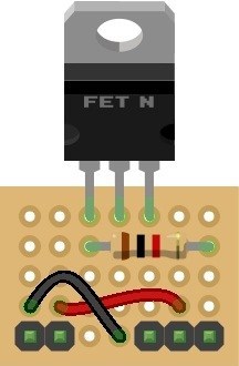
i saw this article while searching over the forum and i would like to add more ports to my ez-b as well but it all seem sort of compliated for me so can you make guys make shematics like rich did on Tip120 & Tip122 Transistor Switching Circuit here is a example photo of what he did or rich can you make me schematics like this thanks
Thats will be like my photo,it is pretty simple circuit and it not too hard to make ,but
I can easy make a board for anyone for about $7 including parts and shipping. (usa) international little higher.
@Metealp97 provided adequate and clear enough schematics and explanations are posted production of a step by step guide like my Switching Circuit one shouldn't be difficult. However, the circuit is only part of the battle, having ARC be able to control the additional ports has not yet been mentioned and I have my reservations about it's simplicity.
Once all of the information has been posted and if it makes enough sense to understand but others are struggling to translate it to terms they understand I'll possibly step in to aid with clearer instructions. Unfortunately I am unable to help as it stands at the moment though.
CODING should be very simple ,its only adding thhe the chip with a high or low signal (bcd)
kinda like this D1 ON,D2OFF,D3 ON ,D4 OFF (i think the would be port 5 on ,using CD4067 CHIP
Need to look at the truth table to be shore
BCD is 1,2,4 and 8 to get 0-16 in decimal
MY last post till i get home
In an effort to push this along since a few are showing interest (at the risk of "the usual" happening), it's all very well saying it just needs high or low on the pins but that's only half the story. It wouldn't be compatible with the build in controls of ARC since you would have 16 devices on one port. The advanced controls such as Auto Position would not function correctly without also running the command to select the correct sub port of this circuit. You wouldn't be able to use the Ultra Sonic sensor with these ports at all, and if you could (by changing for a single port type) the radar wouldn't function correctly as it would not always be receiving the correct information. Using the servo controls wouldn't be as simple you would first need to select the correct combination of ons and offs of the set digital controls. Screen real estate would also be an issue with needing 4 additional set digital controls.
On the scripting side of things you wouldn't be able to have multiple scripts running at the same time if they use devices on these ports either. While script a may be trying to communicate with a servo on port 1 of this circuit, script b may be trying to communicate with a switching circuit on port 2.
There are certainly a lot of limitations to the circuit, I've barely touched on it.
It would be worth while to forewarn of these limitations.
Also, to clarify it would be 0-15 not 0-16 in decimal, just a minor correction but it pays to get everything correct.