Asked — Edited

How To Add More Digital And Analog Ports Tutorial

Started this post on how to add more digital and analog ports to your EZB without losing speed or spending over $70 for another EZB

EDIT 3-31 ITS $69 FOR EZB and to usa its $25.56 CHEAPEST rate without tracking to other countries its a lot more. BOARD COST for circuit is under $3

BUT in my post there is disadvantage and advantages of both ideas ,EZB and multiplexer circuit

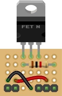
                            PART ONE ANALOG MULTIPLEXING

Analog multiplexing is using only one ADC port and have more then 16 analog inputs and depending on analog ports needed will depend on how many digital ports are used to switch it

VERY simple circuit only one chip under $1 will post a schematic up in a day or 2 and part # of the chip

Its analog switch so it very fast ,not much coding is needed ,not like using 2 EZB and have to pass info back and forth using bluetooth or USB or wifi

Analog ports the EZB only has a few,and needed for analog sensors or other boards like battery monitor ,or current on digital there is more then twice as much

PART 2 will be digital multiplexing PART 3 will be using I2C bus


ARC Pro

Upgrade to ARC Pro

ARC Pro is your passport to a world of endless possibilities in robot programming, waiting for you to explore.

#1  

HERE IS THE CHIP and in a day or 2 can show you how to easy hook up to EZB ,right now in china so i c an make the super simple circuit ,but all is needed is the chip ,.1 mfd bypass cap and thats it on perfboard its CD4051 Here is one link on the price $.52 cd4051 analog multiplexer and the circuit of the chip

User-inserted image

as you can see pin 3 goes in ADC port and 11,10,9 is digital ports ,dont need 3 digital ports unless you need 8 inputs

Another item about using a chip like this ,if a analog port on EZB is not protected from over voltage you lose $70 or more, on this chip only $.51 so you get the more speed,more ADC ports ,ultra low cost and protection of over voltage

#2  

looking forward for the next parts of this project. i am wanting to use it with the polulu ir beacon

#3  

PART 2 GETTING MORE DIGITAL PORTS

this one is hard and 2 ways to do it one is using logic chips

You need TWO CD4066BE $.48 and 1 CD4555BE address chip to get bi-directional data and 4 digital I/O pins to get 8 digital I/0 ,now there is a way to use only 5 digital I/O and get 16 digital I/O'S

PART 3 will be using digital I/O to I2C buss

WILL put up a SCHEMATIC up soon of the circuit

cd4066 datasheet

cd4555 datasheet

#4  

PART3 using I2C PORT

TO get more digital I/O ports there is a very common chip called PCF8574 that has 8 inputs andd fairly easy to use.

pcf8574 i/o expander

chip is $1.64 or ebay has a board from china for $5

pcf8574 i/o expander digikey

pcf8574 i/o expander ebay

NOW for analog the chip is MAX127

8 INPUT A-D CHIP $22

MAX127 8 INPUT A-D CHIP

Pretty soon i will be back home from my work trip and will make the boards

ALSO we be putting up other electronic circuits to help the EZB GET A LOT BETTER

LIKE a tracking microphone i made and only need to charge arduino code to EZB code

#5  

Here is another chip thats cheap and add 16 analog or digital I/O to EZB using 5 lines CD4067 it uses 1 I/O and 4 control lines so in digital you will have 20-5 +16 =31 digital I/O total on analog you will have 8 - 1 + 16 = 23 analog inputs

Speed is same and faster then connecting 2 or more EZB

SOON AS i get home will build all the boards of the circuits i mention and schematic and truth table

#6  

Thanks Fred,

I am looking forward to this. I will have an application for it later on in my build.

Rex

#7  

REX will have the design up after easter,i will return from my trip friday night and build the boards monday and take photos.

COST is well under $3 only a chip,radio shack board and few pins or connectors.

Code is very easy using a truth table using BCD

Will make all designs that day.

#8  

Cool thanks.

One of my favorite chips to use is 74154 (4-line to 16-line decoder/multiplexer)

SN74154

I also like the CD4066.

What's the weather like in China? In what part of China are you staying?

#9  

Robotmaker, are you able to read two ADC values from the same port at the same time using this one chip setup?

#10  

NO not very fast,but there are ways it can be done, FIRST not all time you need to read more then 1 ADC values at the same time,so you just use the other 7 ports for that.multiplexing is fairly fast ,but if data is need much sooner then use 1 of the 7 ports that are left.

MOSTLY multiplexing can be done in micro-seconds,so it depends on your needs

#11  

THAT chip CD4067 is perfect for many sonars using digital I/O and for many IR SENSORS using analog input.

Also if you look at a microprocessor is made they use multiplexing.

#12  

hi all,

i saw this article while searching over the forum and i would like to add more ports to my ez-b as well but it all seem sort of compliated for me so can you make guys make shematics like rich did on Tip120 & Tip122 Transistor Switching Circuit here is a example photo of what he did or rich can you make me schematics like this thanks User-inserted image

#13  

Thats will be like my photo,it is pretty simple circuit and it not too hard to make ,but

I can easy make a board for anyone for about $7 including parts and shipping. (usa) international little higher.

United Kingdom
#14  

@Metealp97 provided adequate and clear enough schematics and explanations are posted production of a step by step guide like my Switching Circuit one shouldn't be difficult. However, the circuit is only part of the battle, having ARC be able to control the additional ports has not yet been mentioned and I have my reservations about it's simplicity.

Once all of the information has been posted and if it makes enough sense to understand but others are struggling to translate it to terms they understand I'll possibly step in to aid with clearer instructions. Unfortunately I am unable to help as it stands at the moment though.

#15  

CODING should be very simple ,its only adding thhe the chip with a high or low signal (bcd)

kinda like this D1 ON,D2OFF,D3 ON ,D4 OFF (i think the would be port 5 on ,using CD4067 CHIP

Need to look at the truth table to be shore

BCD is 1,2,4 and 8 to get 0-16 in decimal

MY last post till i get home

United Kingdom
#16  

In an effort to push this along since a few are showing interest (at the risk of "the usual" happening), it's all very well saying it just needs high or low on the pins but that's only half the story. It wouldn't be compatible with the build in controls of ARC since you would have 16 devices on one port. The advanced controls such as Auto Position would not function correctly without also running the command to select the correct sub port of this circuit. You wouldn't be able to use the Ultra Sonic sensor with these ports at all, and if you could (by changing for a single port type) the radar wouldn't function correctly as it would not always be receiving the correct information. Using the servo controls wouldn't be as simple you would first need to select the correct combination of ons and offs of the set digital controls. Screen real estate would also be an issue with needing 4 additional set digital controls.

On the scripting side of things you wouldn't be able to have multiple scripts running at the same time if they use devices on these ports either. While script a may be trying to communicate with a servo on port 1 of this circuit, script b may be trying to communicate with a switching circuit on port 2.

There are certainly a lot of limitations to the circuit, I've barely touched on it.

It would be worth while to forewarn of these limitations.

Also, to clarify it would be 0-15 not 0-16 in decimal, just a minor correction but it pays to get everything correct.

#17  

SORRY RICH but this chip can be used ,it was done by another person using a different micro.you are right about in decimal it is 0-15 ,i made a so mistake.

THIS CHIP IS USED ALOT IN MULTIPLEXING DIGITAL OUTPUTS

THE EzB has 20 ports so using 4 or 5 still have many left over ,plus gives you 16 more,may be some functions is may not work,

CD4067 is bi-directional chip,and will take any digital siginal,pwm ,pulse,h/l and serial

CANT put up the links on sonars that uses it or servos because it not using a EZB

BUT processor is the same,all processors are mostly built the same

As soon as i get home will make the DESIGN and will hook up a few sonars to show that is works perfect.

ITS a very common chip used for multiplexing ANALOG and DIGITAL I/O,multiplexing is done in micro seconds.

WISH i could put up the links but DJ will be very upset

NOBODY ON THIS FORUM chould say it doesnt work unless they tried it

#18  

I guess email a person who knows about using this chip and is on this forum and will send him much data to show it WILL WORK perfect for EZB

BESIDES me building it and showing that it does work with proof,like VIDEO AND PHOTOS

United Kingdom
#19  

Before carrying out anything one can perform a feasibility study based on the theory and principles behind a design, that is what I briefly carried out and found a handful of limitations. Unless ARC can access multiple ports of the chip at the same time the limitations will stand. It is not necessary to carry out a practical test when the logic behind it proves otherwise.

I appreciate it is you building the circuit and you are free to disregard the information I posted however cannot dispute it with the reply that was posted.

One simple question, a yes or no answer is required, nothing more. Can ARC read/write to more than one port of the chip at the same time?

I know the answer is no as it requires 4 digital inputs to select the port. It is unable to select more than one port at one time as it is an impossibility to apply 2 different digital high or low values to the same port, doing so would select a different port.

For instance;

ARC selects port 6 by giving D0 to D3 high and low digital, resulting in 0110 or port 6.

If you wanted to choose port 8, it would set D0 to D3 high and low digital, resulting in 0001 or port 8.

Selecting both is impossible. Combined would result in the digital high and low of 0111 or port 14.

Without that function the limitations which I expressed (plus others which I did not) will apply. The circuit does not require building to figure that out.

Your argument is weak. I could say to use the ATTiny2313 chip, how do you know it wouldn't work without trying it? Because the information available is enough to make such a judgement. Or to push it to an extreme, you could use a fried chicken to build the circuit, without trying you can't say that it doesn't work. Do you see my point and where I am coming from?

Before getting defensive and claiming that nobody can know until they try please just answer the yes or no question posted, can ARC select 2 different ports of the chip at the same time?

#20  

I guess RICH you no very little about multiplexing,and ezb processor HAS IT INSIDE THE CHIP

CANT SELECT both ports at the exact same time,mostly dont need too

ONE is made and then a few micro second or more or less select the next one

SAME is done on the I2C chip is has multiplexing design and then CONVERTS THE INFO to I2C buss info

SAME IS DONE in a microprocessor like EZB the data is multiplex,same with A-D with 8 ports in the EZB first you have 8 inputs and each one is de-multiplexed by address to get one info out and done very fast microseconds or seconds depending on the design.

SO your question is about selecting 2 different ports at the same time,there is a yes and no can select at exact same time,you need a few micro seconds or less between each port

JUST like how the EZB processor is made.its also done in microseconds or less when it gets the script code and sends it to each output or input,

in the design of a microprocessor i tried to explain it uses a form of multiplexing,since memory only has one I/O most of then and has addresses to select it.

and memory also uses a form of multiplexing since it has I/O and address

On sonars it works much better because you need about 40us (microseconds) before you send the next pulse ,plus the output on the CD4067 is bi-directional like a on off switch or like same as a DIGITAL I/O port on EZB IS

#21  

RICH i can get you some books on about processors and how they work and using multiplexing to help you understand how multiplexing works.

MIGHT make you understand it better,plus if you want many links to others using chips like CD4067 in robots to get more outputs from any microprocessor,all ezb is a common pic processor

Or if anyone else wants this info can send it too.

#22  

I think there is a misunderstanding here (what a surprise!:D ).

I think the question Rich is asking is: is EZ-BUILDER, the great and easy EZ application, can access multiple ports of the chip at the same time... It is not question of the EZB processor capabilities...

Clearly, if it is not usable directly in ARC (at least by relatively simple scripting) and need complex programming to access processors capabilities... I prefer buy another EZB ;)

United Kingdom
#23  

I am fully aware of how multiplexing works and do not require assistance with it. Please refrain from such condescending assumptions it makes it impossible to have a rational conversation with you.

That's a no then, therefore the limitations may still apply.

Script a does not know what Script b is doing therefore there may be clashes, therefore limitations. The GetPing command does not know when to change the port therefore may not be able to use trig and echo as required, therefore limitations.

Limitations and possible limitations must be made clear to avoid users becoming frustrated with a design that claims to add extra ports but in reality may not be compatible with their set up or may return incorrect sensor readings etc.

I cannot explain any clearer. I have not said it will not work. I have not said it will not give more ports. I have said there will be limitations. Please understand what people post prior to becoming defensive, irrational, and condescending.

Continue with your design if you see fit, I shall not be partaking in this subject again. Should anyone require my assistance on this please feel free to email me rich@richpyke.net since my aid is often overshadowed in certain topics - unfortunately this will deny others of the help but I feel it is for the best.

Edit: @fredebec understands (almost) correctly. Some limitations may be able to be overcome with scripting, if loops and an empty port which is selected when not in use for checking to avoid incorrect servo positions or incorrect readings. However it is far from simple, would require a lot of scripting for it to be free of errors and to be honest I suspect the majority of users would not know how to tackle such a script even with examples.

#24  

great hope you dont,

back to my design will post the info and how to make it and find someone if i need help on the code

getping command will test it ,its like any other codes used for microprocessors,but there is a sonar that will. work one wire parallax ping sonar

SEcond i am making the SRF04 work like the parallax ping

ALSO can easy use 2 8 digital I/O MUlTIPLEX CHIPS one for ping and other for echo,so it can work.

FIRST TEST is i will do is manual select the sonars,i see that arduino board usesc the same idea to select different sonars and DJ said it fairly easy to convert the code So that might help me with the coding

very bad for others to say it does not work unless they tried it

BUT also this chip can be used for other digital I/O ,DOESNT HAVE TO BE ONLY FOR SONARS ITS ONLY ONE EXAMPLE.

BUT testing is the best proof,i havent tried it with EZB yet so i cant say it works or doesnt work only can say it DOES work with arduino and other pic processors

THEN THERE IS always EZB-SDK since there is a code for Csharp in another site that uses 16 sonars with only one digital ouput using a multiplex chip like this one,and can easy convert to EZB-SDK using the C sharp

#25  

@Rich, I have voluntarily simplified your words... to make the message as clear as possible and prevent another misunderstanding. ;)

But still I have subtly edited my post to be more correct...

#26  

PLEASE wait till i am done before anyone says it can or cant be done

I try to explain it easy for other to understand

AND i know alot about them since i have used them alot at work with my designs ,only coding i left for other departments and my circuit was perfect with them.

ONLY one design was change by them a little.

I am more of a expert on using multiplex chips,since of my long time testing and designing.

ON RICH coding it may or maynot be a problem until its fully tested ,but like in the other post instead of using 16 digital ports multiplexing can use two 8 multiplex chips and you getping info is solved

BUT also there is parallax that uses one digital line,and i have a simple circuit to make SRF04 work just like a parallax one wire PING sonar

#27  

THIS design may or may not work for all types of inputs ,very hard to tell will testing it first. I dont think i might have a problem with the coding since it looks simple

BUT there are many many other uses on ezb THAT CAN USE IT.

HERE is good question why does the internal circuit in EZB MICROPROCESSOR that uses multiplexing in design can use it to address the digital 20 ports and not the CD4067 ,same type of chip design?

United Kingdom
#28  

ARC was built to use the EZ-B. The EZ-B is fully supported in ARC in all of it's functions. ARC was not built to support other microprocessors.

The main difference is your circuit is not addressed via the D0 to D19 ports. It isn't as though it adds D20 to D28 or D20 to D36. Therefore the functions built in to ARC will not work correctly with your design. Code and/or set digital controls are required as I have already pointed out.

All answers to your questions can be found in my posts. You may need to read between the lines a little but the reasons are there.

And again, not once have I said it will not work other than the ultra sonic sensor and GetPing if it is on two of these additional ports. I guess you aren't very good at reading, I can suggest some books to help, The Cat In The Hat is a good start.

For the record, I have not said I would not help with the scripts. Anyone who intends on using this design despite it's limitations is more than welcome to ask for assistance with the scripts to select the correct port number. Each script, each function and each robot will be different so I would not expect generic code to be posted in this "tutorial".

Edit to help the coding question just after I posted: A typical example script for selecting the desired port would be;


# Enable sub port 11
Set(d0,on)
Set(d1,on)
Set(d2,off)
Set(d3,on)

#Enable sub port 5
Set(d0,on)
Set(d1,off)
Set(d2,on)
Set(d3,off)

Each and every port needs the correct combination of ons and offs to set the correct port. It is done via a binary method so port 0 is 0000 or all off, port 15 is 1111 or all on, port 1 is 1000, port 2 0100, port 3 1100, port 4 0010 etc. Understanding binary to decimal is a huge part in selecting the correct sub port.

Once that is done then you send the command to the microprocessor i.e.


Servo(d4,50)

I'm sure you can see how much extra code is needed, how much more complex it becomes and how the conflicts may occure should two or more scripts run at the same time both needing to communicate with a device on the microprocessor.

End Edit :)

Now I am done with this topic. Do not refer to me if you do not wish for me to reply.

For anyone else, if they require my assistance please contact direct at rich@richpyke.net or start a new topic. I will not even be checking this topic again (and with that in mind please refer back to my earlier posts when deciding if you will use this circuit or not, I'd hate for you to be unsatisfied with the results).

Lots of love, hugs and kisses, Rich :).

#29  

@Robomaker, don't get me wrong, having the possibility to add more digital ports to EZB could be interresting in big robots and big projects. But an easy integration in ARC is mandatory for me. It should not be more compex to handle that using 2 EZB.

You say that the coding shouldn't be a problem "since it looks simple"... Can you post a quick example of scripting or simple coding? I am interrested in evaluating the level of difficulty.

PRO
Synthiam
#30  

If you were to add more ports to the EZ-B, you will sacrifice communication speed. I do not recommend adding a multiplexor to the EZ-B for large projects.

By the time you source the materials, solder the breadboard and write the code... Your time is much better spent building robots and buying a second EZ-B. :)

#31  

DJ FIRST looking to sell the boards about $6 or less,and the coding might be more if you use a second EZB,then you are loooking at a drop in speed using 2 boards,needs to use bluetooth on both boards

Plus at back and forth communication.

Cant see how you would lose speed since is digital then using EZB with bluetooth,thats where speed it lost.

Most likely code will be made by me or someone else

IT only uses one chip ,plus radio shack board,plus connectors or straight wire ,no other parts. :)

United Kingdom
#32  

Using a second EZ-B would need no extra code other than the board number in all controls and EZ-Script commands. All native controls in ARC would work regardless of port and board used. All EZ-Script commands would also work.

Not only would it be much simpler to use two boards, and tie that in with the costs of extra code (think of it as time writing scripts is time not doing something else, I value that time highly) it would be both easier and cheaper in the long run to run 2 EZ-Bs.

Your design will always have it's limitations as previously expressed. The GetPing EZ-Script command would not function correctly if the sensor is on two of these sub ports. Script commands on two or more scripts running simultaneously may have problems, which poses as a huge limitation on any of my projects as I have 4 or 5 scripts running at any one time, sometimes more.

All native controls would no longer be supported and would require scripts to operate, as a minimum 4 Set Digital controls to select the correct sub port so that the other controls would operate would be required. Running this with scripts running in the background also would pose a serious problem.

The same limitations would apply to an I2C based extender, which I had looked in to and decided against, however I2C would pose the simpler and less conflicting of the two methods. Native controls would not work correctly, if at all however the conflicts with scripts would be avoided.

Personally I would not wish to script around these limitations or script the extra code required to select the correct sub port. And this is the recommendation from someone who enjoys writing scripts. The extra code would be an educational guesstimated 5 times as much as that of using a second EZ-B.

Simple logic knowing both how the chips work and how ARC/EZ-Script work dictates that the above is correct and 100% justified in it's conclusion - building a practical circuit would have no benefit in finding the conclusion.

Not forgetting the issues DJ has mentioned also.

There are some applications where I can see the benefit of using this circuit however the limitations and extra work required greatly outweigh the benefits. To put it in plain and simple terms, it's a $60 saving in exchange for a lot of headaches.

This is for the benefit of those who are deciding on which method to use. This is not an argument against any design and as such is not open for debate. Users may use this post as they see fit and are free to disregard it should they wish to. All datasheets and documentation has been digested prior to this posting.

#34  

MAIN problem most overlook is the speed of the bluetooth ,compare to speed of digital chip witch is less the microseconds.

You see that first you need to send info to the second board and then to port you want to use and then receive the info back using bluetooth again.

NOW using a digital chip you dont have that problem ,but there may be limitations ,just like in USING 2 EZB'S ,havent tried it or anyone else tried it too

Like the getping WILL NEED TO TRY IT,might be a easy fix for it.

I guess best way is the testing of it.

BUT check the speed of the bluetooth communication and compare to digital.

ANOTHER item others dont look at is size of the EZB and extra current it needs.

Adding the board is just like adding another sensor or using the serial command to another board

#35  

I see mostly nobody really try it (like me)so its kinda hard to say it may or may not have problems.

Its not made for every sensor or digital add-ons ,but it does help.

ONCE i build it witch takes less the hour only a few pins to solder will test for different add-ons

PLUS there are same chips that uses 4 output with one in,and 8 out 1 in ,so it uses less control lines to control it.

United Kingdom
#36  

A (very) quick Example Project for testing the circuit.

Imagine the circuit built, two servos connected to sub ports 0 and 1 (or 1 and 2 depending on how you name them)

D0-D3 are the control ports. D4 is the passthrough. Two servos, set to D4. Two scripts, one which sets servo on sub port 0 to a low position randomly the other that sets the other servo to a high position randomly.

Run each at different times and you have no problems. Run both together and there will be times when the low position servo hits a high position and vice versa. The control portions of each script fight each other for control of the digital ports. ARC does not know the servo positions for the two servos and believes both to be the same.

This is with only two devices. Imagine the confusion and problems with having 16 devices on one port.

A major problem if limits are set on one servo and another pushes it past those limits, possibly causing physical damage.

This is just one limitation I mentioned.

One does not need to build the circuit in order to know the outcome. multiplextest.EZB

And again, this is for the benefit of those who are deciding on which method to use. This is not an argument against any design and as such is not open for debate. Users may use this post as they see fit and are free to disregard it should they wish to. All datasheets and documentation has been digested prior to this posting.

Please, build the circuit. Test the circuit thoroughly. The limitations mentioned will be there, I personally guarantee it.

Netherlands
#37  

Wow, will you two ever both just agree on a statement?

#38  

I have a large project with lots of things going on and a few constantly running scripts. I've ran my robot on both 2 boards and now 3. One of the boards is fully loaded with Digital and ADC ports filled. The other two are less then 1/4 filled. At first when I started using 3 boards I had an issue with one or two Bluetooth connections disconnecting. Also I had bad lag problems with all my scripts running variables and monitoring ADC ports. The internal Bluetooth on my older laptop running Win 7 couldn't handle the extra load and it was a bottleneck. Following DJ's advice I disabled the internal Bluetooth and started using a USB 3.0 Bluetooth Dongle in one of the laptops 2.0 USB ports. That solved my connection and lag problems using 3 boards.

Never had slowdown or connection problem with using just two boards connected to the laptop with the old internal Bluetooth set up. And I had a lot going on in ARC.

However last night I tried to use a different "2.0" USB Dongle in place of the 3.0 Dongle. I started having the same old issues till I put the 3.0 back in. Also had the same results on a different Laptop from the same era. So, there is a speed issue with Bluetooth and Dongles are all not created equal. I have a feeling it's the way the Dongle is made and how good it's antenna is.

With all that said it still seems that the better choice would be to get a second (or third) EZB Board and to avoid the many other pitfalls described using Robotmakers idea. To avoid the Bluetooth bottleneck one could convert EZB to Wifi or USB. Still Robotmakers board would be an interesting experiment to try. ;) Early on DJ himself suggested to me in another post to "get inventive" and try to come up with a way to multiplex an ADC port to make two connections to it. Someone suggested using a simple resistor. I'm not knowable enough to do this but (personality aside) I'm glad it's being discussed and tried. :)

#39  

Thanks DAVID,but kinda hard to tell if the EZB is faster then using a straight digital board

IT seems i qam always wrong with RICH ,but its not a problem

Testing the board is the best way.

#40  

ON multiplexing analog ports there are many ways to do it with out using resistors.

KINDA hard to read one vaule with 2 resistors sending the same data at the same time,how does it know witch resistor has the data without a switch

on multiplex chip it is like spdt switch,now you can use 4066 witch is a single switch .

United Kingdom
#41  

@robotmaker, I have not said you are wrong. Please re-read my posts.

#42  

YOU are right and i dont need to read it again,i understand all posts you did,so may be a bad choice of words. YOU JUST disagree wih me try to understand that RICH

Just nobody did any tests on using the board so they cant say much about the design unless they build and test it.

i have about 20 ezb boards can very easy use for my projects instead of the digital multiplex circuit

BUt main item every board you use it raises the current much higher,but on using the CMOS chip current is super low.

PLUS like DJ its slower the EZB because of the commucation speed.

United Kingdom
#43  

Not at all. I have not disagreed with you either other than you saying it needs to be made before anyone knows if it will work.

What I have done is exposed the limitations on this design, explained them and made you and other members aware of them so that you and they can made an informed decision on whether or not to use the circuit or choose to use another EZ-B.

I have said that this circuit may be of benefit in some applications, I do not believe it to be a complete waste of time and effort. However the limitations must be totally understood so that the users are not left unsatisfied with the results or worse, end up physically damaging their projects due to those limitations.

For instance, I can see this circuit being useful to control the different coloured LEDs inside my robots brain, an action which would require at least 5 digital ports for the basic plan, more on my more advanced plans. However it would pose problematic if I wanted to use this circuit to control the pan/tilt bracket on my robots neck, to control his arms, to control the H-Bridge, to control the ping sensor or sweep servo.

As I have attempted to make perfectly clear, my posts have not been to discredit or dispute any design but are purely to inform the forum users of the limitations which would be present in this design.

#44  

THats what i meen by the limitations i am also saying the same about using 2 EZB boards it has limitations too.

You have 16 leds you need to control ?

On servo's i dont think it will work,on sonars i think it will work because its used many times to control 16 of them,

I think the way is was done is 16 outputs used to get echo ,or send ping that received or send the ping is using 8 digital ports.

SO on the getping function you use the digital port on EZB like you said there is problem with that and on send signal use the digital port.

NOW i know others wont use 16 sonars ,maybe 8 ,but thats 16 lines ,so 8 on the multiplex circuit and 8 on the EZB.

DO YOU UNDERSTAND THIS.

AND total cost of ezb is not $60 but close to $75 or more depend on the country you live in

WOW re-edit on cost its $69 for ezb and to fla its $25.56 is the cheapest rate

United Kingdom
#45  

I cannot and will not explain any further when it is perfectly clear in previous posts.

Also check your logic and check your maths. 16 sonars, that's 16 x 2. 16 on the multiplexer and 16 on the EZ-B so as to avoid the limitations right? So it takes 4 control ports and 1 pass through port for the multiplexer for 16 devices. That's 5. Plus the 16 for the echo of the sonar, that's 21 ports used on a 20 port board.

#46  

Yes,but not saying to use 16 sonars ,and i guess you dont understand what i said aboout using half the ports on EZB and half on multiplex circuit.

I said nobody would use 16 sonars maybe 8 ,so only 3 address lines and 1 I/O and you save 4 ports and if you use all 16 ports the other 8 ports can be used to drive relay's or leds or ?

0-7 I/O is address is 1,2 and 4 0-15 I/O the address is 1,2,4 and 8 THEN the getping function wont be a problem using only 8 ports idea.

I am trying to explain the advantage of using the multiplex design over the EZB to me over $100 is a lot for second EZB in my robot ,plus as DJ said that speed is much less on EZB because of communcation and then high current draw.

So other need to know the disadvanges of using a second EZB too.

United Kingdom
#47  

Perhaps I mis-inerprited;

Quote:

I think the way is was done is 16 outputs used to get echo ,or send ping that received or send the ping is using 8 digital ports.

SO on the getping function you use the digital port on EZB like you said there is problem with that and on send signal use the digital port.

Quote:

NOW i know others wont use 16 sonars ,maybe 8 ,but thats 16 lines ,so 8 on the multiplex circuit and 8 on the EZB.

Has that been edited by the way? It started at 16, dropped to 8, back to 16 and ended at 8... ;)

Also, DJ said

Quote:

If you were to add more ports to the EZ-B, you will sacrifice communication speed

That doesn't mean using multiple EZ-Bs, it means adding more ports to one EZ-B.

Please enlighten us on the disadvantages of using a second EZ-B, other than the cost.

#48  

OR i didnt explain it correctly and i meant 8 not 16 it takes 16 lines for 8 sonars ,8 pings and 8 echo, ping is the start pulse and echo is the receive in PWM I guess i didnt recheck my post wanted to get back and have my dessert at the party FOR EASTER.

I thought he meant you lose communication speed using 2 EZB witch you do.

Way a processor is made is that is has memory ,plus digital circuit ,timers and then uart communication circuit and clock circuits AND MORE before it gets to the digital port.

With a digital multiplex circuit is straight communication ,no bluetooth or uart or clocks or memory or digital circuits.

I dont think many knows how a processor really works and the circuits inside,coding and using is easy.

JUST follow the path on the processor that is use to see how slow it is and compare the path with multiplex chip.