ARC Pro

Upgrade to ARC Pro

Harnessing the power of ARC Pro, your robot can be more than just a simple automated machine.

#1  

According to another post, the EZ-B(4) can operate on 3.3vdc. DJ uses a 5vdc bench power supply to test his EZ-B(4). You might consider using 5vdc to operate the board and a separate 12vdc supply for your servos.

#2  

I sent them an email and apparently someone from ez robot would have answered this. Oh well

#3  

Also, how can you hook up 20 servos to a single 12v battery?

#4  

lol, when you post in the forum, you get a forum answer.

#5  

"Hi (REMOVED),

Do you mind asking that question publicly on our community forum? We'd love to give the response there so people looking for that info in the future can easily find it.

Thanks!

Alan"

i have no idea why this was done but they asked so i just moved my email question here

#6  

@Cupcakehat , welcome to the community

The tracings on the board are limited to the power they can provide. It's best if your going to go with a direct power source to skip the board. You would run a power wire to a distribution block and all the red positive servo connections would be connected to this. This bypasses the microcontroller board direct to your 12 volt battery. In most cases a servo is not rated for 12 volts unless it is a large very heavy duty servo. The servo specs will say if it can handle 12 volts. Most take either 5 , 6 or 7-7.4 volts. The only 12 volt I know of are dynamixel that I can think of.

  • Josh S
#7  

Correct, it's a dynamixel 12a. 20 of them, and i don't wanna do anything bad to them, so i'll try your idea. Thanks! :D

(P.S., where could i get 4 way battery splitter? I need to get 4 6-port 12v distribution blocks. eyeroll)

United Kingdom
#8  

This has been discussed here

User-inserted image

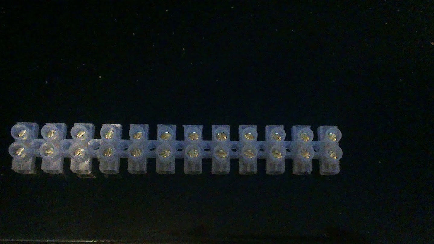
These little 5A guys come in handy for distribution (as do their bigger brothers who are rated at 20A)

#10  

OK, so i've looked up a 12v distribution block, and all I can find is those huge fuse boxes. Any links for a distribution block that can handle 12v that has atleast 10 ports? (Also, do you have to solder the wires to the block?)

#11  

Also, where can i get the little ends that have a hole to connect to a signal plug? I only need the one plug hole if you have to solder the wires.

United Kingdom
#12  

The connector blocks are rated in amps not volts. How many amps total are you going to be expecting to pull via one of the connector blocks?

The little ends are JST connections. You can buy a crimper and the ends however the crimpers are quite expensive (at least over here they are) and they are fiddly. I tent to cut jumper wires and servo extensions and solder them up as I require them. Or you could just use servo extensions, cut the red and black off close to the plug and leave the white for the signal. Just be careful not to short red to black.

#13  

i bought a crimmper about 4 years ago and it was around $45 usd. then i lent it to my father who promptly lost it.;)

United Kingdom
#14  

They are about £80 over here, that's $100-120 ish... which is why I solder up the cables... Would love a crimper so I can do all my wiring perfectly though.

#15  

I use spade crimp connects and a 8 dollar crimper. You can use quick connects as well which are also crimp on. The spade connectors fit onto the barrier strip terminals perfectly.

#16  

The max Amperes a dynamixel itself can handle is 900 mA, so can i get a link for what i've said before that can handle that.

United Kingdom
#19  

@Doc is that a seller you have used yourself? I ask because I have bought cables and some have been totally useless so now I stick to a seller I know sends good stuff.

They are what I use. Cut the wires and solder on jumper wires, cover with heat shrink (or tape if you're on a budget) and viola, you have the cable you need.

@Josh, are these the crimps you use?

User-inserted image

I prefer to use these terminal blocks;

User-inserted image

They do them in 3A, 5A, 15A and 30A they are also totally enclosed so no chance of something dropping on them and shorting anything.

For the common ground I like to use these;

User-inserted image

#20  

RichThe link provided is to a seller I use, and the cables work fine. Of the ones I've used, none have been defective.

#21  

@ Rich , yes that style crimp spade connectors. They never come loose and i use the barrier trip for extra protection you can spray or paint on liquid rubber and it makes the heads of the screws insulated but i just place a piece of tape over the top and all the connections are completely covered at that point. I use white tape so i can write on it with a sharpie to label what the connection so are. I did this on my fish tank controller

#22  

There are silver and gold plated versions , turns out silver is more conductive but gold yells that you spent the extra money.

User-inserted image

I just use stuff like these silver plated and insulated connectors.

User-inserted image

User-inserted image

#23  

Can anyone sketch up a way to do this? It needs to fit in a humanoid robot that is 17 in. tall (custom, built upon bioloid frames & dynamixel 12a's) and fit into a small backpack on the back. Help would be appreciated.

#24  

Do you have the bipedal robot frame yet assembled with pics. I could draw some general ideas. Take in mind a backpack effects balance , he would need to lean forward like a hiker.

#25  

It's pretty much a bioloid, but with 4 extra servos (two more dynamixels and micro servos to rotate each wrist) until the head comes, then it will be a bioloid with 6 extra servos. (the JD head)

I don't have a camera yet, but when (if) this robot is finished, i'll find some way to take a picture.'

EDIT: He also has a changed leg frame. Instead of having the bend part for the knee joint, he has another long straight piece.

EDIT EDIT: So at the middle joint of the knee, this frame piece: http://www.trossenrobotics.com/store/p/6179-Bioloid-Frame-F1.aspx is replaced with this: http://www.trossenrobotics.com/store/p/6182-Bioloid-Frame-F4.aspx

#28  

CupcakehatBasically you could use the white lead as the signal control wire from the EZ-B and cut the red and black leads and run battery power to each servo from your 12 volt power source.

#29  

then could I just power the 6v / 7.4v servos straight from the board using a 6v power supply to the board?

#30  

If you use a 6 volt source to power the EZ-B then it could also power the 6 volt servos but the 7.4 volt servos won't be getting the optimum power for operation. Also you need to consider what the total servo amperage will be. I believe that the EZ-B has a 4 amp limit.

United Kingdom
#32  

A quick search found they have 35mA stall current (however I do not know how reliable the information is) therefore you have 4 which may pull 35mA each...

4 x 35mA = 140mA

Check the stall current though, I struggled to find it and only found it in one place which required a calculation (subtracting the controller's current draw from the total draw to leave only the servo's current draw) so it's possibly not too accurate.

PRO
Canada
#33  

I wanted to reply to this thread right away, but we are still finalizing the specs on the EZ-B v4 so I can't share anything official yet. I can say these things though:

  • We do feel that operating the board from 12V batteries is important
  • The board will be able to operate 24 servos but as @Robot-Doc mentioned, you will need to consider current draw/battery life when operating that many
  • Specs (Voltage min and max, and Current max) will be shared with you soon

I hope you guys are as pumped for Revolution as I am!:D

#34  

The humanoid robot is all ready to go, and if it can handle 12v servos (with 12v battery), then i can have my own little humanoid! Thanks! :D