This is a video to show you guys how good the Kangaroo/Sabertooth motor controller combo is!
Dave, this video starts by showing the ramp-up - full speed - ramp-down algorithm that I coded on the PIC microcontroller, you will see how GET_POS is read and controls the ramping up/down. The ramp-up and ramp down rates can easily be change via a variable. When I get my V4, I will port the algorithm over to an EZ-B script for those that want it.
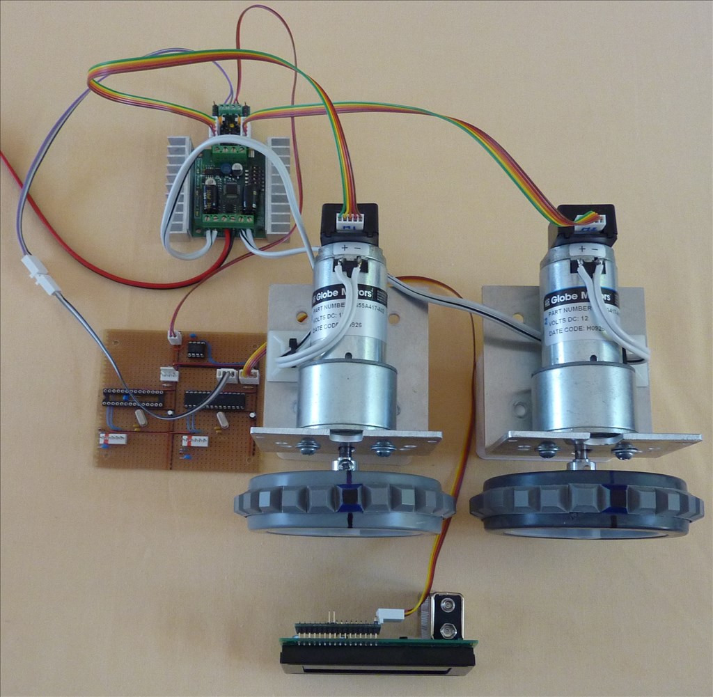
The second part is to show you folks how important encoders are, here you can see the incredible synchronising that the Kangaroo's auto-tune PID has. I have sent it precision movement (distance) commands for hours with barely no loss of motor synchronisation which means that you can build a robot that will accurately move in a straight line and move/turn to the exact distances that they have been previously programmed/taught. I use this for accurate room mapping and having pre-learnt routines which enable my robots to move from one room to another or to a particular room location.

@Tony, what you're doing with the Roo/Sabertooth amazes me. Sadly your work with the PIC is way over my head but I do understand the basics of what you're doing. When you describe your theories I feel like Dr McCoy listening to Spock on the bridge of the Enterprise in Star Trek. confused However I'm not going to call you a "green blooded Hobgoblin" though. It's all good because the intent comes through and makes sense that way.
I have my dips on the Roo set the same so I should be able to get the same results as you with the proper script now that I have my V4 (hopefully).
One point I'm unsure about is where on the V4 to get the serial feedback from the Roo. I thought it would be read through on of V4 EZB's digital ports. I thought this because we send serial commands through the signal pin of a digital. Now you say it should read serial feedback from the i2c port. confused I guess I need to get this cleared up.
I have the same question. I posted a thread about it late last night. Per @RobotDoc's suggestion, I bought a i2c to UART converter to read the serial feedback which I'm hoping will accomplish the same function as @Tony PIC. I don't know how to use it but i'm hoping it will do the job. Any thoughts? Conversely, is it very difficult to program a pic to do what yours is doing with the v3? I've never used one.
Dave, apologies for any confusion (I am getting old!), the Roo is bi-directional serial connected (not I2c), as I only have a V3 I had to use a PIC to do the conversion from b-directional I2C (from V3) to bi-directional serial for the Roo.
I am using encoder feedback (of position) you will be using potentiometer, but I do think both will require the same coding.
Going back to my original algorithm, first your script needs to know if the move you require is long enough to require ramping as with very short moves ramping becomes irrelevant.
After this you need to compute the "ramping-down" point of the move (say 10 - 20% from the end position).
Now you can use "getp" (get position) to find out where you are in the move this would look like
Serial out = CHN,getp,13 where CHN is channel number (in the case of a single motor this would be 1 or 2)
The above should return the current position and would look like this
Serial in = CHN,p,2500,13 - here the lower case "p" means that the move is not completed
or
Serial in = CHN,P,3000,13 - here the upper case "P" means that the move is completed
If you want ramping down at the end of motion then you need to work with the lowercase "p" as if you wait for the uppercase "P" then its too late as you would have obtained the end target position. So you would start by issuing a position command like
Serial out = CHN,p,3000,13 where 3000 is the position you want to move to
Then you start a loop that continually checks "getp" to see if you have attained the "end less %" that you computed at the start (say) 2500
After every "getp" you need to check the position and exit the loop if it has hit the computed ramp-down position, something like this
If POSITION > 2500 then goto RAMP_DOWN - we use "more than" here because of the latency of reading the serial back we could overshoot the computed value.
I have not covered start ramp-up as that is the easy bit.
Hope this is of some use.
@Tony,
Getting Old? It seems like what you have going on in your head is a thousand times more fertile than most 20 year olds. The confusion is my fault. I just cant keep up with you. Anyway, I got it all worked out through out the day yesterday and actually got my motor to move by sending a serial command from my V4's UART port to the Kangaroo. It was not controlled or exact but it was a thrill to see it happen. I knew I was on the right track when I sent the "Start" command and saw the little LED on the Roo blink.
  DJ's Example Project on using the UART port and some kindly guidance by forum members really made the difference. I gotta keep reminding myself that I'm not as smart as I think sometimes and that if it wasn't for the guidance and help from people like you, Rich and others and not the mention the hard work DJ has put into the manuals and videos there is no way I could do this stuff. It would take a lifetime (not much of which I have left) to get the education to do it on my own.
Also, I had not considered using the lowercase "p" to help with the ramp down part of the script. That makes since as it's the incremental position command. Sometime I have a little problem wrapping my mind around that sort of thing. blush
As always, thanks for your guidance and help.
The V4 has bi-directional serial through the UART ports. The whole reason the PIC is being used is to bridge the gap left by the V3's send only serial.
Tony has said that when he gets his V4 he will port over the code to EZ-Script, so yes, the V4 will not require the use of a PIC.
Looks like Tony is using the PIC in place of the EZB. His PIC has two way serial and the V3 EZB does not.
I haven't worked on the two way serial thing a lot yet with my V4 EZB. I've been busy retrofitting them into my B9 and getting them to work on him system by system. I was able to get my waist motor to move by sending a serial command through UART 0 but that was about all I tried.
Matt, I looked at those magnetic encoders on your link and they look like they are going to be very low resolution, in fact so low that you may find it hard to get any accurate feedback from a single turn. Generally people use high resolution (optical) encoders, the ones I use have 64000 clicks for just one wheel revolution so the position accuracy is incredible.
On the I2C to serial converters, I have never used these, but I think the idea might work.
@Tony My challenge with the optical encoder was getting one to fit my shaft diameter (17mm) without costing an arm and a leg. My robot is a rover of sorts. Do you think a solution could be to add a more powerful magnet? I have some larger neodymium magnets somewhere. I also happened to order two sets so perhaps I could tie two together somehow? Otherwise can you recommend an encoder? Your motors are fairly large.
As for the converter, I didn't realize it will be coming from china so my v4 may arrive before the converter does. I just ordered my v4 a few weeks back so i'm way at the back of the line. I'd like to get this v3 going as it is the only robot project I have right now. I understand that you make robots professionally from your forum posts. Do you sell a pic board that may accomplish this feature with the V3 per chance?
I finally received my USB-to-TTL serial converter so hopefully I can at least upgrade my kangaroo firmware.
Appreciate all of the information you have provided.
warm regards Matt