PRO
rb550f
USA
Asked
— Edited
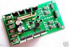
Dual Motor Driver
I have a dual motor driver that has 6 pin connection for motor control...pin 1 ground ..pin 2 pwm2..pin3 dir2..pin4 pwm1...pin 5 dir1.....pin six +5v...how should i connect this to ezb with movement panel...

Without the manual or data sheet, your guess is as good as mine.... If it's an H-bridge... Rich should be able to help you....
It is a dual h bridge.
Motor forward: DIR = 1 PWM = PWM Motor reversal: DIR = 0 PWM = PWM Parking brake: DIR = X PWM = 0 (X is an arbitrary state) Motor and power connections POWER connected to the positive power supply, GND power supply is negative. Two motors were connected MOTOR1, MOTOR2
Parameter:
Rated voltage: 3v-36v (can be customized according to the user) Rated Current: 10A Peak current: 30A Use: Freescale smart car contest Undergraduate Electronic Design Contest variety of DC motor control circuit Dimensions: length 108mm*58mm width
include:
New Dual Motor Driver Module board H-bridge DC MOSFET IRF3205 3-36V 10A Peak 30A
Exactly how it says...
Pin 1 - EZ-B Digital Port Ground Pin 2 - EZ-B Digital Port Signal Pin 3 - EZ-B Digital Port Signal Pin 4 - EZ-B Digital Port Signal Pin 5 - EZ-B Digital Port Signal Pin 6 - Regulated +5V
Assuming you are using D0, D1, D2 and D3
Connect D0 black to Pin 1 Connect D0 red to a 5v regulator Connect D0 White to Pin 2 Connect D1 White to Pin 3 Connect D2 White to Pin 4 Connect D3 White to Pin 5 Connect the output of the 5v regulator to Pin 6
Either script or use PWM and Digital controls to operate.
D0 needs a PWM control, this controls the speed of motor 2 D1 needs a digital on/off control, this controls the direction of motor 2 D2 needs a PWM control, this controls the speed of motor 1 D3 needs a digital on/off control, this controls the direction of motor 1
Or scripting, to move a robot forwards would need the following script
For reverse
Turn one direction
Turn the other direction
Stop
Speed control is done via PWM on D0 and D2 if you need it.
It's the same method used by the Dagu motor controller, as explained in this topic
Thanks .I just wanted to make sure i was it doing right.Thank you for your help..
Two quick questions about this controller as I have just received one.
If I supply 12v to this controller via the "power" terminal with one battery, do I still need to connect the EZ-B4's "positive" digital pin to the +5v terminal on the controller, and do I need a regulator as the EZ-B4 is powered via a separate 7.4v battery?
What's the correct GND terminal on this controller to connect a common ground from the EZ-B4 to? I ask as this controller has two GND connections.
I'm asking as I am swapping out an L298 controller for this one.
Thanks.
Steve G.
What does the manual say? Is there a manual?
Basically, it will still need +5v from somewhere for the logic circuits, if it doesn't have an onboard regulator (the L298n does) then it will need a +5V from somewhere.
You have a common ground with the EZ-B, connect both grounds to the common ground. You can do this simply by linking the two or by taking two separate grounds back to a ground point.
No. It didn't come with a manual which is why I'm asking. I know the L298 has an onboard regulator as I have been using one (with white button pushed down) but wasn't sure if this controller had a regulator on it (again, no documentation with it). I followed the instructions above, but @rb550of didn't mention what voltage he was using to power his motors so I wanted to be sure before I hooked it up.
@Rich.
Sorry, I forgot to say thanks for replying and clearing that up for me. So just to clarify as I've never installed a regulator, a 5v regulator needs to go between the EZ-B4 ground and possitive pins on say D0, and the +5v and GND pins on the controller? Sounds like a silly question but I just want to be sure. Actually having a little trouble finding an in-line 5v regulator from the UK.