Asked — Edited

Dslr Camera Trigger

Hi! This is my first post here!

I have built a robot before using the arduino, but now really want to make something useful. As you can see in the video, my last robot didn't really do much, it was just REALLY big!

Video here

So I am going to try an make a DSLR 360 robotic panorama head, controlled by a smartphone.

The robotics part, I am pretty sure is more than possible with ezrobots hardware / software. But would it be possible to trigger a Nikon d750 with the EZ-B v4/2?


EDIT:  The final thing is pretty much done! See the videos of it working below. 


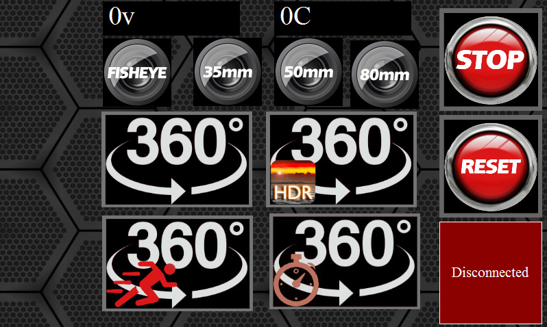
And here is the mobile phone app interface. User-inserted image


ARC Pro

Upgrade to ARC Pro

Unleash your robot's full potential with the cutting-edge features and intuitive programming offered by Synthiam ARC Pro.

#1  

Do you have any specifications on what is required to trigger the camera? I see from some searching that it can use an IR or cable release, but we would need to know what the cable does. If it is simply closing a switch, should be pretty easy to do with an EZ-B digital port and probably a transistor. If it is more complex, then so would be the solution.

The EZ-B can't directly do IR, but there are probably solutions for this too (A robot gripper holding an IR remote control aimed at the camera is a down and dirty way to do it. Crude, but effective).

Alan

PRO
Synthiam
#2  

Mostly the button is a simple switch - which you could do with a solidstate relay. It would be pretty easy to create the whole thing!

EZ-Robot's video guy made a pretty neat rig for time lapse, but he used a go-pro

#3  

Brilliant!

So I could actually make it refocus first too by using two relays. By the looks of it anyway. I found someone made one for a Canon. The jack is a simple stereo jack and the same in the Nikon.

User-inserted image

So there are enough pins on the EZ-B v4/2 to do this. Perfect.

Many thanks! I really appreciate the quick responses!

#4  

For greater control and to have 360 degree capabilities, I am thinking of using something like this for the pan motor. What do you think? Compatible with ezrobot hardware?

http://www.01mechatronics.com/product/supermodified-v30-rc-servos

#5  

Here is how they would suggest you connect it to the Arduino. So would it work with the EZ-B v4/2? If so, what are the equivalent pins to the ones shown on their website?

Thanks! :D

http://www.01mechatronics.com/support/gettingstarted/testarduino

PRO
Synthiam
#6  

Hey, no double posting threads:D tsk tsk

Yeah those servos will work. They have serial or i2c connectivity. So you can choose either one or the other. In practice, the serial/uart is much easier to work with. Use the SendSerial() EZ-Script command and voila! :D

Just have to take a look at the manual to see what the commands are to move the servo.

PRO
Synthiam
#7  

Oh, according to: http://www.01mechatronics.com/support/gettingstarted/testarduino

They say...

Quote:

3.4 Connections legacy RC interface

The connections needed for legacy RC interface are illustrated below. Note that according to 01TM Supermodified firmware, standard PPM pulses can be interpreted in different manner, allowing e.g. for speed instead of position control. Also the angular range can be manipulated with different firmware. Please let us know your requirements and a custom firmware will be available as soon as you ask.

So that will be the easiest! Simply get the servo and ask for it to receive standard RC/PWM between 1-360 degrees. Voila :D

Although you can use the servo that Jamie Young uses with his BB8. It's called a Winch servo and that is easier to find.

PRO
Synthiam
#8  

This winch servo has 1260 degree rotation! That's awesome: http://www.robotshop.com/ca/en/hitec-hs785hb-servo-motor.html

And here is another winch servo that is cheaper: https://hobbyking.com/en_us/sail-winch-servo-13kg-0-7sec-360deg-55g.html

That's what you need :D

#9  

Ok cool, thanks. That's really good to hear.

Sorry about the double post. I am the new guy haha :p

Anyway.. I plan on attaching the magnetic sensor (pot replacement) on the turntable itself rather than in the servo.. I can get more of a direct reading then. Not sure it this is a good idea or not.

I will have to add gears for the pitch and yaw mechanisms as the camera and lens are about 1kg. The load will be about 5cm from the fulcrum for the pitch. My RDS3115MG servos I will modify, have 17kg/cm @ 7.2v. I figure, if I gear it by 6x, I should have enough torque and be safe not to overload it.. It will hopefully hold in position nicely too. It will be a lot slower though.

PRO
Synthiam
#10  

That's a good idea, to move the pot. That way you can increase the torque for sure.

#11  

Oh! I didn't see your post about the winch servos!

That's even better:D And they are weatherproof too..

Because I am based in South Korea, it can be hard to find decent stuff at a good price, especially imports! But I found a HS-785HB 3.5 for $10 cheaper than USA sites :D

Thanks dude! Great help!

#12  

Spent last weekend doing some test prints / designs / ideas..

So I have adapted a servo with gears to run 370 degrees. I wanted a bit of overshoot for the 360 degree pan, just to be safe.

I just moved the pot so it is now geared. I will do a smaller version this weekend.

I printed this one in PLA as hear it is better for gears. Any ideas on printing gears in different materials? What is best in your experience?

User-inserted image

#13  

Here are two other vr panoramic heads I made. The small one was the first, for a go pro hero 4 black.

The larger one is for my DSLR.

They snap incrementally into place manually - but only for one lens. The DSLR is set up to snap into 16 positions around 360 degrees and 4 positions on 180 degree for the vertical. Only for a 50mm lens.

Both printed in ABS.

So if I want to change the lens, I need a new base for snapping positions.. This is why I am making a robotic one instead..

I thought I would use this thread as a log for my progress if that's okay?

User-inserted image

#14  

I got my delivery on Monday! Had a play with it and made a simple app on my mobile to move a servo. Seems to work great!

Got to say, that was the easiest setup I have ever had! Thanks!

Looks like I might end up buying the mini one too as I really don't need all the features / outputs on this beast! (At least for this project anyway):D User-inserted image

PRO
Synthiam
#15  

Hi! Totally use this thread for your progress - it's a good place for it because it tells a great story :D

Looks like it is coming along well!

#16  

Cool thanks.

Because of other commitments, I'm giving myself 8 weeks to finish this! Should be fine, as long as I don't need to order any parts from overseas. Will definitely need some advice when it comes to the coding though..

Will post some more progress after the weekend :)

#17  

Can you guess what it is?

Busy designing and printing the mechanism for panning. User-inserted image

#18  

So, after this build of the 360 degree panning system, with a modified digital servo, I have realised that if I want more accuracy of the positions, I am going to need another solution.

It has the power due to the gearing. However, in the software I am using to make a 360 vr panorama, I can save a template, so I don't need to stitch the images semi-manually every time. For this to work, I need pretty good accuracy as the software expects each image to be the same incremental angle for the template. Really useful feature.

So my next attempt would probably be using steppers with H-bridges to control them.

User-inserted image

#19  

Here are a couple of threads about using steppers with the EZ-B.

https://synthiam.com/Community/Questions/5028

https://synthiam.com/Community/Questions/6183&page=2

Alan

PRO
Synthiam
#20  

Yeah - a continuous rotation servo wont' give you the accuracy because I suspect you're triggering the servo ON/OFF real quickly to get small steps. However, due to inertia, the gears will continue to move even with the tiniest of pwm pulse.

You will have much better luck with the winch servo. Because you can specify degrees of accuracy and the servo will hold the position.

#21  

I actually moved the pot to a gear. So the servo isn't continuous. I am going to give it one more try, using a different gearing setup.

Thanks for the links to the steppers Thetechguru! It will be really handy if I do go that way..

I do have a few 12v 380kg/cm servos that do 1.5 turns laying around too. (Overkill much?) I really dont want to use them for this as they are 1lb per piece! Also going up to 12v just complicates things. Don't want to risk losing fingers either haha!

Back to the electronic drawing board >__<

#22  

Ok awesome! I managed to get more accuracy now for the pan axis with a modified servo. (The link to your modified servo (continuous rotation servo) happens automatically - can't see how to stop that ~ but it still isn't one of those lol)

My gear system for the pot was a little loose, so redesigned those gears. Much tighter fit now and I can't move / wiggle the pot gear manually with my fingers.

So now that tricky bit is out of the way, I can work on the next axis. This one needs more torque as will be lifting over 1kg at 4cm to 5cm ~ depending on which lens.. These servos are 17kg/cm so if I gear it to a 3:1 ratio, it should have 51kg/cm ~ that comes out at 10.2kg of torque at 5cm.

#23  

Update.

So I spent the weekend printing and assembling. Got a first prototype working. The only problem I am having is my wobbly tripod head! The actual panoramic robot is really rigid. I have printed a new tripod head that is much stronger, but the weekend is over and have no time to fit it tonight.

To add extra stability to the two axis, I used some massive thrust bearings. Seems to do the trick.

At the moment, it is all printed in PLA, just 1.2mm walls and 20% infill. Not sure if this will be up to the task for long-term use, so when I have everything right, I will print it again in ABS, 100% infill.

All that is left to do now is to design and print a detachable electronics housing / battery holder. It should balance it out nicely too. Then print the adjustable camera mount. Should have the camera on there by the end of next weekend!

So here is a video of the prototype in action. I used a cardboard box in place of the camera.

#24  

What a contraption. Very cleaver. Love it. I can see this has been a lot of work and brain power on your part. Nice work!

Your design looks very solid and the servo movement is so smooth. Sweet! However what are you going to do about the wobble your tripod is adding to the mix? I would imagine if your software is expecting a smooth transition from shot to shot and your shooting quickly you would want the pan to be exact. Is there a new quality tripod in your future? :D

#25  

Thanks. I think it is a bit overengineered for what it actually does. The tripod head is crap though. You spotted it in one.. So wobbly. This tripod cost $20 haha! A quality tripod might be a good idea yes!:D For now, I have printed a much more solid mounting system to replace the cheap and flimsy device that came with the tripod (That is in contact with the entire surface of the mounting plate on the robot) but didn't have time to attach it yet. Will give it a try later and post the results:D You're dead right about the software expecting the same degrees of movement. The servos are ok. It all depends on how they hold up under the weight of a dslr. The next step, if they start juddering under the strain, will be to replace them with steppers.. Hope I don't need to go down that route though..

#26  

Hey, looks like I will be needing some technical advice.

I am going to need two relays to trigger the focus and shutter control.

Incoming newb questions!

  1. What kind of relays would you recommend?

  2. Where do I plug them into the main board?

  3. What kind of code would I use to trigger them?

Many thanks in advance to anyone willing to help!

:D

PRO
Synthiam
#27  

We used some solidstate relays for the Bimbo The Clown hack. Maybe @Jeremie will chime in on the pcb we used for that.

#28  

Thanks. I hope someone knows! It Should be as simple as using a high and low command if it is the same as the arduino. Do d0 to d23 output the same voltage as the power supply?

I believe I just need to use a NO (Normally Open) relay.

To make the connections for focus and shutter I will use two relays.

So d0 to d23 have the ability to send a pulse right? Do they work with commands like "High" and "Low"?

If so, all I need to do is set it to High, with a sleep for timing, and then back to low. Not sure what the code would be exactly, but along the lines of

#focus for 3 seconds Set(D0,on) Sleep(3000) Set(D0,off)

#Shutter 1 second Set(D1,on) Sleep(1000) Set(D1,off)

Here is what I need to control with the relay.. User-inserted image

#29  

So I was thinking of using an optoiso. After trawling the web, I found a few people favoured them with things like the arduino, because they are very simple to use, and small.

No emf feedback either. I was thinking a 4N35 or similar..

Anyone have any experience with these?

#30  

Got my cable to go to my DSLR through the post for the camera focus / trigger.

I saw some people are using a opto isolator in conjunction with a relay - to make sure that there is no EM feedback from the relay. Does anyone know if a solid state relay can damage the pin / board if used directly? Or is that a mechanical relay only?

#31  

Used a couple of 4n35's last night. Made the circuit on the breadboard and successfully have the Nikon focusing and taking a picture.

Luck wasn't my friend yesterday. The cable I ordered for the Nikon shutter release didn't work. So drove to the centre of Seoul the get a new one.

Anyway, the road was hell because of the millions of protesters outside the bluehouse! Loooong journey for a cable!

Will solder this morning. Love the smell of flux in the morning!

One observation. The 4n35 works with the ez @ 7.2v. But 6 isn't enough. Using the signal wire with the set(d1,on) commands.

#32  

Camera trigger PCB all soldered and working.

I added an extra cable and plug to the camera trigger I got for the Nikon in Seoul yesterday. Now if I want, I can unplug it and still use the trigger button on its own.. I hate waste!

Now to put it all together with the panorama robot. Just got a couple of minor things to print first. Should have it ready to test by the end of the day!

User-inserted image

#33  

Designing a quick UI for the three modes.

Got options for normal, HDR and quick capture so far. A reset button to go home / abort capture.

User-inserted image

#35  

Thanks Dave! :D

Printing the final parts now. The camera mounting parts are being printed in ABS. I am printing with 100% infill and think I might give them an acetone vapour treatment to make sure they are as strong as they can be. I hate that part! I will carefully test it all first though.. Down to the last minutes of printing :D

#36  

Adjustable mounting system for the camera works. Had to make it adjustable so I can find the 'no parallax' position for different lenses.

Note the new tripod mount too. It now screws directly onto the tripod.

User-inserted image

#37  

I don't have a battery yet. Have to wait until next weekend to print the electronics / battery housing. Just printing a simple one for the electronics for testing purposes. I hope that by next Sunday I can do an outdoor test! For now, I am plugged into the wall.

#38  

The servos have no problem moving the camera. Just need to find a sweet spot for speed / accuracy now :)

#39  

Off to the electronics stores later to find a better quality potentiometer for the servos. I tested it earlier and it seems to be 5k.

The ones that came with the servo are quite flimsy. Will try and find something metal / stronger design.

#40  

Got these on my lunch break. Both 5k pots. One is a regular pot - just much stronger that the one that comes inside a regular hobby servo. The blue one is a 10 turn pot.

Will try both later and see if I can get better results with higher quality / stronger built pots!

User-inserted image

#41  

The 10 turn pot works so smoothly! Cost $5 each, but WOW! What a massive difference! User-inserted image

#42  

Still haven't decided on batteries yet.

Some batteries have problems with international travel at the airports. However 6 rechargeable 1.2v aa batteries should make up the voltage, and never had a problem with them at airports.

Have to do more research this week about this.

The plan is to take the final one around Europe this New Year for three weeks, and the UK for two weeks for a proper field test. Not long left! :D

I will take a few spare parts and as many batteries as the airline will permit.

#43  

Just curious, what issues were you having when you were using the old pot? I have an old cheap multi turn pot that I'm using for feedback and am not happy with it smoothness I'm getting from my control system for this motor. Maybe I'll follow your lead and get a better quality feedback device.

#44  

Because I had it geared down so it would make a quarter turn for every one turn of the pan axis, I am guessing this was going the wrong way about it. Now I have the pot turning 2 times for every quarter turn of the pan axis. The 10 turn pot is just a geared pot as you know, I guess the factory manufactured gears are much higher quality than anything I can print.

It's really nice now! Busy for a couple of days but will put a video up before the weekend with any luck.

I may had damaged the old pot too. I had the shaft of the pot inside a 10mm shaft, supported by a bearing, but I think it still had a bit of strain on it.. I am just not good with the fiddly little things >__< damn sausage fingers! haha

#45  

Been refining some ideas of the code this morning.

My code is so simple compared to most projects here! No ai for a start.

Looking at what people have achieved here is really inspirational! There really are some clever people around.

I would love to build another robot. I was working with air muscles a while back. Trying to figure out a decent control system using valves controlled by servos.

Might have to come back to that when i'm done with this!

#46  

Off to an RC shop in Gangnam tomorrow morning for battery shopping. This evening I will be testing all the routines I set up, routing the wires, and having a general tidy up.

Sunday I can do my first field test if weather permits! Then back home for processing the photos!

#47  

Got the battery and charger this evening as can't wait haha. I went with a 1300 7.4v for now. See how it goes with power consumption. User-inserted image

#48  

I was just getting into the coding yesterday evening when my workstation motherboard died!

So I'm on my backup now while I wait for a new motherboard. Damn!

Anyway!

The battery is working great and seems to last a long time too.

Now I have to print a few final parts for housing the electronics and battery.. Tidy the cables etc..

#49  

This battery has lasted all day so far with a full day of testing indoors!

The releaseall() command was a stroke of genius.. Thank you for making it so easy!

#50  

As my old app is on my busted PC, made a new one. This time I have a lens selection too. Different lenses need different amount of pictures.

Added a time exposure button too. Might add a slider for changing the timed exposure setting.. User-inserted image

#51  

Off for a first field test this morning. :D

#52  

In action this morning.

Bit noisy during morning prayer at the local temple! They were lovely and brought me some coffee out :)

#53  

And this is taking the final vertical shot, then resets back to the home position.

#54  

I gave myself 6 weeks. 5 Weeks later and it is 95% done. One more week to refine everything and do some more test shoots and it will be ready for my trip!

Thanks so much to the community / management for all the help. Your help was just the right amount to guide me in the right direction.

The ezrobot is a great piece of hardware. The software helps make it so easy to turn your ideas into something real!

Thanks! :D