
woodylv
USA
Asked
— Edited
Df Robot L298p Twin V1.1 Motor Shield
Has anyone had any experience with this motor controler.
Is a DF Robot L298P-Twin V1.1.
I went to DFrobot.com and couldnt find any info on it.
What I am trying to do is to run two servos for the arms on my Bot.
Any suggestions would be appreciated.
I am going to continue to search but you guys have been so helpful so I though I would attack on two fronts 
Rich if you can anwser this one too I owe you a pint if I make it to the UK.
Thanks,
Michael

Here is the URL Once there you will see both a link for the manual as well as a Schematic.
Hey Doc, Thanks for the info.
My board is slightly different. The number is DRI0017 instead of DRI0009
How ever the boards look the same but the issue is trying to find where I connect the 5v too and also where I connect my EZB too.
Also do I need to create 2 pwm modules in my project ?
I am not getting any lights on the board. not sure if I am supposed to or only when the motors are moving?
If you know of a spot on the boards I can look for more info that would be great too.
What I am trying to do is drive 2 motors to make my arms go up and down. (That's it)
I thought it would be easy but I might have bought the wrong boards. Not sure I got 2 of them.
Right now I have the bot moving via the wheels. which is using a sabretooth 2x24 motor controller. in serial mode.
This was easy since there was a object for the sabretooth. But I can find out how to add this.
It says its arduino compatable. The name on the board is l298P Dual Twin v1.1
Hope that helps.
Thank you guys for the support
Michael
Data sheet
You have your motor connections which should be self explanatory. You have your power connections, again should be self explanatory.
The control truth tables should be pretty simple to follow. I'll have a better look later if this isn't as straightforward for you. But basically it looks like you have pin 4 to pin 7, Pin 4 & 6 is direction control, high to go one way, low to go the other. And pins 5 & 7 speed control, PWM 0 for off, PWM 100 for full speed.
I have only had a quick look at this as I have limited time right now but if you do need more help with it I'll take another look.
Looking at it again, the datasheet I linked to is the same as the one Robot-Doc linked to.
From what I can work out, you need to use pins D4 to D7 on the motor controller. And you need to set the jumpers for PWM
On the motor controller; D4 - Direction control. Set High or low with the Set(digitalport, On/Off) command i.e. Set(D15, On) D5 - PWM/Speed control. Set the PWM value for the speed of the motor with PWM(digitalport, speed) i.e. PWM(D16,100) D6 - PWM/Speed control. Set the PWM value for the speed of the motor with PWM(digitalport, speed) i.e. PWM(D17,100) D7 - Direction control. Set High or low with the Set(digitalport, On/Off) command i.e. Set(D18, On)
Going from memory, the Dagu controller works in a similar way. I believe there was an issue stopping the motor and a low PWM was needed before the 0 PWM or Set off command... i.e.
Rich,
My board doesnt have jumpers.
It does have a table listing the E1 M1 and so on.
Lets start with what objects I need to create in ARC?
Thats what I am realy having an issue with.
Also I found out what was going on with my EZB board.
My sabre tooth has a 5V circut that generates power for the Microcontroler not needs 5v.
So stupid me I needed to isolate my power circuts. I was providing 10v and browing out the board.
Going to fix that later.
I am using the EZ B GUI interface should I be using the SDK ?
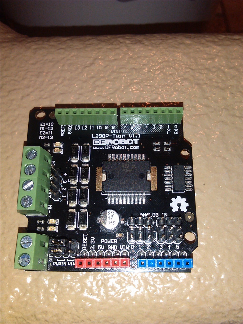
Here is a pic of the board and of the packaging with the different SKU. (This is why its not matching up)
All I want to do is drive two screw motors up and down.
Thanks as always for the help and discussion.
No need to use the SDK, you can do what you need to do in ARC.
Looking at the picture you need to replace the D4-D7 in my last post with 10-13 to marry up with the different E1, M1, E2 & M2 as detailed on the board.
What you need in ARC is (provided you can't add another Movement Panel assuming you have added the sabertooth on), you will need; Direction controls - Digital Control or Script to Set(Digital Port,On/Off) Speed controls - PWM control or Script to PWM(Digital Port,speed)
I'll see if I can find anything more on that board when I get home.
Update: No, it seems nobody has any information on the DRI0017 only the DRI0019.
Rich ,
I am obviously missing something.
Here is what I have.
I got the motors and the 12v in connected.
The only jumpers I have are for the power which I have set to Pwr in. (Meaning the shield is using the 12 v in for the motors)
Then I have ports 10 - 13 hooked up to ports D1 - D4 on the EZ B
So what I am not sure of is how I set up the PWM and Digital Ports.
What I am doing is adding one digital set object for each motor
And one PWM object for each motor
I am not sure if the PWM should go to the e's or the m's
Then I am not sure how to make the servos or motors move. I.E. how do I add a Movement Panel or modified servo panel.
I read your turtorial on the H Bridge but that is for a movement panel.
I am not sure what I am not following here and I am sure its something small and stupid but I am having trouble wrapping my head around this.
If you could help me find clarity on this I would be greatful.
Thanks,
Michael
If you already have the sabertooth control panel you can't add another movement panel. You can only have one movement panel. It'll be easiest to run scripts to move motor 1 forward and reverse and motor 2 forward and reverse.
This is assumption based on the documentation for the DRI0019 and the photo of your board, I cannot guarantee that it's correct but it shouldn't be far off.
The easiest way to check if it works is to add Digital controls to ARC. A Digital On is the same as a PWM of 100%. So add 4 Set Digital controls for D1, D2, D3 and D4. Set D1 and D2 to On, see what happens. Toggle D1 and see if it starts and stops the motor or reverses the direction. Do the same for D3 and D4.
Once you know which port does what you need to write your scripts for forward and reverse for each motor.
For example, if D1 and D3 starts and stops the motors and D2 and D4 changes the directions;
Motor 1 forwards
Motor 1 Reverse
Motor 1 Stop
Do the same for motor 2 with ports D3 and D4
It may be a lot of trial and error to get it set up. Once you have worked out what does what then we can look at adding speed control if it's required.