
hamchenko
USA
Asked
— Edited
I don't know how I stumbled on this site a week ago but since I've started reading about everyone's projects, in that week I've already purchased my Omnibot on eBay and put in my order for my ARC kit.
I've been fascinated with robots since I was a kid and been a mild tinkerer all my life, but never have I tried to embark on a project of this magnitude. The closest I've gotten to a robot in my adult life is the tattoo of a robot I have on my leg.
Just a fair warning, I'm sure I'll be on here asking a million questions during my build process. Thanks everyone in advance for all your help.
Adam

If you do not know how to solder, you had better get a buddy that knows how to do this for you. Lots of people around can save you many headaches later. It is a skill that it takes time to learn.
Just my 2 cents.
Mel
That is great advice. I have done soldering in the past so not to shabby. I am practicing on old computer boards and scraps so when it gets to the real deal I won't "glob" it up. I really do not want to destroy the real parts, so after this weekend I should be ready to finish my light chaser kit.
Thanks for making a good point, I need all the help I can get,..
Thanks MovieMaker!!
Folon
Question: Do I still need an H-Bridge with the 2.5 Amp Motor Controller to drive the motor? I thought the Amp Controller would do it all without an H-Bridge,..
Folon
The 2.5a motor controller is an H-Bridge actually.
No, you don't need an H bridge if you are using a motor controller (it is the H bridge). Here are some pics of the drawing from above that might help with your light chaser.
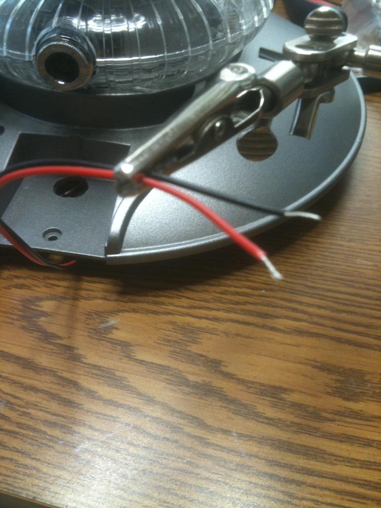
this is the red and black from the lights.
this is the red, white, and black of the servo connector wire.-634735535168281250.jpg)
this is the TIP120 and 1K resistor-634735536412968750.jpg)
The resistor is tied to the white signal wire.-634735536891093750.jpg)
Then soldered to the transistor-634735537226406250.jpg)
The black from the lights goes to the center pin and the black from the servo connector wire goes to the other pin of the transistor.-634735538051718750.jpg)
Tie the two red wires together (to get power from the EZ-board) then protect it all with heat shrink tubing or electrical tape.-634735538742031250.jpg)
Hope this helps!What happened to the diode going from Emitter to Collector? What was it's model number?
Thanks Ndavid79 and Bret, I thought so but wanted to make sure,..
Wow does that ever help, thanks,.. Im printing these out now. I am sure this will help a lot of other people too. Thanks for your efforts. BTW I am not doing good with my $6 solder iron, im ordering a Hakko - FX-888. It has great reviews and I see they last forever. This will get better soldering done.
Wow, Thanks,.. impressive,..
Folon
You only need a diode when it is an inductive load like a motor. I don't know which diode it is.