
Arduino PWM Bearing Control Help
Hi @Athena,
I'm requesting help to add capabilities to an existing Arduino sketch. The sketch is included at the end of this post. Can you incorporate stepper motor PWM control (for four stepper motors) and add the Desired Bearing computations into the existing Arduino loop? Thank you in advance.
For clarity, here is the system context:
- ARC (Synthiam Autonomous Robot Control) runs on an EZB4 and provides the high-level navigation, vision, and script coordination.
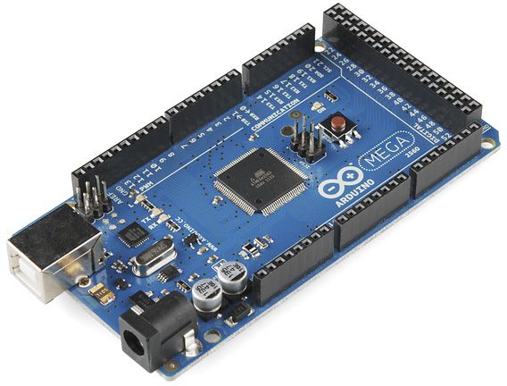
- The Arduino Mega handles real-time hardware tasks (stepper motor control and Desired Bearing calculations). Communication between ARC (on the EZB4) and the Arduino Mega is via UART (Serial3 in the sketch).
- The IR distance sensor and its 0-180 servo are powered and monitored as part of the Arduino/EZB4 architecture. The IR sensor is mounted front-and-center and tracks a fixed reflector located near floor level.
- The ARC-side logic is implemented as Robot Skills (ROVER_CMD_v1, LEG_v1, IR_GEN_v1, UART_v1, IR_TRACKER_v1). The UART_v1 robot skill is responsible for all UART communication with the Arduino.
- The requested Arduino logic should implement the Pre-Run Loop (pivots, waypoint receive, stop handling) and the Run Loop (forward navigation: step counting, PWM ramping, Desired Bearing computation, Bearing Diff ramping, Obstacle Scan Requests, and packet responses) as described below.
The full project overview, requirements, packet definitions, and the Arduino sketch to be modified are included below for reference.
ARC Rover: Arduino PWM Control and Bearing Computation
PART 1. General Overview
PART 2. Term Definitions
PART 3. Requested Criteria for the Arduino Sketch
PART 4. Arduino Sketch to be modified with PART 3 Criteria
PART 1
General Overview for informational purposes:
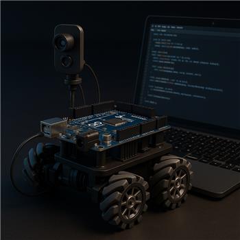
This rover is driven by 4 stepper motors rolling on 4" mecanum wheels and powered by a 24v 5000mAh lithium battery. Individual buck converters supply the appropriate DC voltage to the EZB4, Arduino Mega, IR distance measuring sensor, and the IR sensor servo. The IR sensor is mounted to a 0-180 degree servo centered at 90 degrees. This gives the IR sensor equal travel left (180) and right (0) of center (90). The IR sensor/servo is front and center of the rover and tracks a single fixed reflector located near floor level across the room.
The principal purpose of this rover is to explore and develop a navigation system based upon the Sharp IR distance measuring sensor. Overall controlling architecture is accomplished via Synthiam ARC on the EZB4. Certain high CPU demands such as stepper motor control and Desired Bearing computations are accomplished by an Arduino Mega. Necessary communication between ARC and the Arduino is via UART.
This rover project is very much a work in progress. Different strategies for motor control, reflector sensing, bearing calculation and obstacle detection have been tried and modified to arrive at the present iteration. What follows represents the latest embodiment of this rover project.
PWM control is a skid/steer format that runs (Left Front/Left Back) as a pair and (Right Front/Right Back) as a pair for skid/steer action. Other mecanum wheel capabilities will be developed as necessary.
ARC Rover Control Architecture:
Individual ARC Scripts for Overall Rover Control
1. ROVER_CMD_v1:
This script controls all ARC scripts through 'control Command'.
2. LEG_v1:
This script defines the Waypoint Data for the rover path. It sets global variables necessary for each leg and operates only once.
3. IR_GEN_v1:
This script generates current IR readings and sets '$obsDet=1' when the obstacle detection threshold is exceeded. It operates in a continuous loop.
4. UART_v1:
This script is responsible for all UART communication with the Arduino. It operates in a continuous loop, acting upon global variable status.
5. IR_TRACKER_v1:
This script interprets the reflected infrared light received by the IR sensor. Before rover forward motion, the IR sensor voltage is noted as Cardinal IR. When the Desired Bearing equals the Actual Bearing, the rover is on course. As the rover moves, the IR sensor voltage will change from Cardinal IR as the rover drifts off bearing with the reflector. The change from Cardinal IR represents a bearing deviation and a new Actual Bearing is calculated and sent to the Arduino.
PART 2
Term Definitions:
Actual Bearing: The actual angle between the IR sensor and the reflector. ARC calculation.
Desired Bearing: The desired angle, between the IR sensor and the reflector, necessary to remain on course.
Arduino calculation.
Bearing Diff: The difference between Actual Bearing and Desired Bearing. Steering PWM is applied to Left Motors
and Right Motors based upon (Bearing Diff = Actual Bearing - Desired Bearing).
Actual Bearing is sent to the Arduino by ARC as an X100 representation.
EXAMPLE (Actual Bearing of 79.00 is sent by ARC as 7900). Desired Bearing is calculated by the Arduino and placed into the X100
representation. Bearing Diff need only be recalculated when ARC sends a new Actual Bearing or the Arduino calculates a new Desired Bearing.
Leg always refers to the physical track of the rover. Measured in inches and converted to Combined Steps. One inch = 437.5 Combined Steps.
Leg Start Point: The beginning point of navigation.
Leg Stop Point: The end point of navigation.
Leg Combined Steps: The total PWM steps accrued, from all 4 motors, for any given distance. One inch = 437.5 Combined Steps.
Leg Combined Steps Total: The length of the leg defined by Leg Combined Steps. The distance between the Leg Start Point and the Leg Stop Point.
Leg Combined Steps Taken: The distance traveled in Leg Combined Steps.
Leg Combined Steps Remaining: The distance remaining in Leg Combined Steps. (Leg Combined Steps Total - Leg Combined Steps Taken).
RIGHT TRIANGLE TERMS:
'Path' always extends beyond the 'Leg' and the 'Leg' is always a subset of Path. One inch = 437.5 Combined Steps.
'Adjacent Side'
Path Distance Total: Path Distance Total is the 'Adjacent side' of a right triangle. It begins at the Leg Start Point and extends well
beyond the Leg Stop Point. Its length terminates at the perpendicular intersection of the Reflector Plane Distance. Measured
in Leg Combined Steps.
Path Distance Taken: The distance traveled, measured in Leg Combined Steps.
Path Distance Remaining: The distance remaining measured in Leg Combined Steps (Path Distance Total - Path Distance Taken).
'Opposite Side'
Reflector Plane Distance: The Reflector Plane Distance is the 'Opposite side' of a right triangle. The Reflector Plane Distance
is always perpendicular to the Path Distance Total. Its length is a fixed distance, measured in Leg Combined Steps,
between the Path Distance Total and the physical reflector.
PART 3
Requested Criteria to be added to the Arduino Sketch:
1. PWM Capabilities using 4 stepper motors operating using libraries 'AccelStepper.h' and 'MultiStepper.h'
AccelStepper LeftFrontWheel(1, 3, 6); // pins
AccelStepper LeftBackWheel(1, 2, 5); // pins
AccelStepper RightFrontWheel(1, 12, 13); // pins
AccelStepper RightBackWheel(1, 4, 7); // pins
Pre-Run Loop: Pre-Run Loop is the default loop and is active only when Run Loop is deactivated.
Monitors for the following packets/commands sent by ARC:
Each pass through the Pre-Run Loop:
1. Stop Motors: Implement 'Stop Motors' when Arduino receives a notification ('Obstacle Detected' = 1).
Respond to Stop Motor command by sending 'Total Steps Taken' to ARC.
2. Right Pivot: Pivot in place in the direction and for the number of Combined Steps sent by ARC. Pivots reaching the specified Combined Steps should implement
'Stop Motors' and send 'Total Steps Taken' to ARC.
3. Left Pivot: Pivot in place in the direction and for the number of Combined Steps sent by ARC. Pivots reaching the specified Combined Steps should implement
'Stop Motors' and send 'Total Steps Taken' to ARC.
4. Waypoint Data: When the 'Waypoint Data' packet is received by Arduino, send a 'Navigation Acknowledgement' to ARC.
Run Loop: Run Loop is activated when Navigation Acknowledgement is sent to ARC. Pre-Run Loop is deactivated.
Monitors for the following packets/conditions sent by ARC:
Each pass through the Run Loop:
1. Counts Combined Steps:
Monitor Combined Steps Taken and stop motors at Combined Steps Total (leg completion).
2. Motor starting PWM is applied with a 'ramp' up to normal speed. Incremental ramp steps accrue during each pass through the Run Loop.
When normal speed is reached, this ramp up to normal speed is terminated.
3. Monitors when Actual Bearing changes are sent by ARC. Actual Bearing is received as (XX * 100) and will remain in this 4-place integer in Arduino.
4. Calculates Desired Bearing at selected intervals.
Desired Bearing is converted from XX.XX to (XX.XX * 100) and remains in this 4-place integer.
Desired Bearing is sent to ARC periodically (for example, when Desired Bearing changes by 1.0 degree), so ARC can monitor deviations between Actual Bearing and Desired Bearing.
(See SUBSECTION: DESIRED BEARING CALCULATIONS below for more on Desired Bearing)
NOTE: Whenever Actual Bearing OR Desired Bearing changes, a Bearing Diff must be calculated.
5. Bearing Diff:
a. Bearing Diff is reset to '0'. Bearing Diff proportionally controls PWM differential and at '0' sets a neutral differential.
b. A new Bearing Diff is calculated. (Actual Bearing - Desired Bearing = Bearing Diff)
c. Bearing Diff is 'ramped' from '0' to the new Bearing Diff. Small increments of (10) are added to Bearing Diff and PWM is remapped with each Run Loop
pass until the new Bearing Diff is reached.
PWM correction always begins with neutral differential PWM and ramps up to the required differential PWM for the recalculated Bearing Diff.
Example: Actual Bearing = 8800 (88.00). Desired Bearing = 9000 (90.00). Bearing Diff = -200. (8800 - 9000) = -200
Bearing Diff is set to '0'. Each pass through Run Loop accumulates an additional (-10). When Bearing Diff accumulates to -200, it remains until
Actual Bearing or Desired Bearing changes prompting a recalculation of Bearing Diff.
Actual Bearing = 9200 (92.00). Desired Bearing = 9000 (90.00). Bearing Diff = 200. (9200 - 9000) = 200
Bearing Diff is set to '0'. Each pass through Run Loop accumulates an additional (+10). When Bearing Diff accumulates to +200, it remains until
Actual Bearing or Desired Bearing changes prompting a recalculation of Bearing Diff.
6. Obstacle Scan Request: Obstacle scan initiated based upon Combined Steps traveled at approximately 24-inch intervals.
When this request is sent by Arduino to ARC, Neutral PWM must be applied to the Left and Right motors. Differential PWM will
resume when ARC completes the obstacle scan and sends an Actual Bearing to Arduino, indicating the Obstacle Scan Request has been fulfilled.
7. Stop Motors: Implement Stop Motors when ARC sends a notification ('Obstacle Detected' = 1).
Send Total Steps Taken in response to the Stop Motor command.
SUBSECTION: DESIRED BEARING CALCULATIONS
Desired Bearing is calculated entirely by the Arduino in ONE of two ways (A or B):
A) If Waypoint Data received indicates Bearing Alignment 0 (DA), then the Desired Bearing is fixed and never changes, remaining at 90. [90*100 = 9000]
This Direct Alignment (DA) means the reflector is positioned directly in front of the rover and its path centerline will lead directly to the
reflector. Desired Bearing is never recalculated.
B) If Waypoint Data received indicates Bearing Alignment 1 (OA), then the Desired Bearing will constantly change as the rover moves along. The
Desired Bearing may, for instance, start at 83.00 [8300] and end at 71.00 [7100]. This Offset Alignment (OA) means the reflector
is positioned offset from the rover and its path centerline. Desired Bearing is calculated at Combined Step intervals of 100.
The trigonometry calculation of a right triangle is used for an Offset Alignment (OA) reflector:
Tangent = Opposite (Reflector Plane Distance) / Adjacent (Path Distance Remaining)
If Waypoint Data received indicates Track Direction = 0 (FD), then the following is applied for forward direction:
Path Distance Remaining = (pathDistanceTotal - abs(legCombinedStepsTaken));
If Waypoint Data received indicates Track Direction = 1 (RD), then the following is applied for reverse direction:
Path Distance Remaining = pathDistanceTotal - (legCombinedStepsTotal - abs(legCombinedStepsTaken));
if (desiredBearing < 90) {
desiredBearing = (atan2(reflectorPlaneDistance, PathDistanceRemaining) * 180/PI) - 90;
// a positive angle is required, use the absolute value
desiredBearing = abs(desiredBearing);
}
// Use atan2 to calculate the angle correctly
if (desiredBearing > 90) {
desiredBearing = (atan2(reflectorPlaneDistance, PathDistanceRemaining) * 180/PI) + 90;
}
PACKETS:
ARC -> Arduino Packets:
1. Stop Motors (rover full stop)
Byte Value
Header 0xA5
Command 0x01
Payload none
Packet size: 2 bytes
2. Actual Bearing (Bearing to the reflector)
Actual bearing is sent as a whole number scaled by 100.
Example:
79.00 degrees becomes 7900
sent as a 16-bit unsigned integer
Byte Value
Header 0xA5
Command 0x03
Byte 2 Low byte of bearing
Byte 3 High byte of bearing
Packet size: 4 bytes
3. Right Pivot
Byte Value
Header 0xA5
Command 0x04
Byte 2 Low byte of step count
Byte 3 High byte of step count
Packet size: 4 bytes
4. Left Pivot
Byte Value
Header 0xA5
Command 0x05
Byte 2 Low byte of step count
Byte 3 High byte of step count
Packet size: 4 bytes
5. Waypoint Data
Byte Field Type Notes
0 Header 0xA5 packet marker
1 Command 0x06 waypoint packet
2-5 Path Total Distance uint32 max 120000
6-9 Combined Steps Desired uint32 max 84000
10-13 Opposite Distance uint32 max 24000
14 Bearing Alignment uint8 0 = DA, 1 = OA
15-16 Reflector Bearing uint16 scaled by 100
17 Sensor Prime uint8 1-10
18-19 Desired Bearing uint16 scaled by 100
20-21 Actual Bearing uint16 scaled by 100
22 Track Direction uint8 0 = FD, 1 = RD
Packet size: 23 bytes
Arduino -> ARC Packets
1. Navigation Acknowledgement (confirmation of Waypoint Data received)
Byte Value
Header 0xA5
Command 0x10
Payload none
Packet size: 2 bytes
2. Total Steps Taken (response to Stop Motor command)
Use a 32-bit unsigned integer.
Byte Value
Header 0xA5
Command 0x11
Byte 2 Total steps byte 0
Byte 3 Total steps byte 1
Byte 4 Total steps byte 2
Byte 5 Total steps byte 3
Packet size: 6 bytes
3. Desired Bearing (course computed for desired rover path)
Byte Value
Header 0xA5
Command 0x12
Byte 2 Low byte
Byte 3 High byte
Packet size: 4 bytes
4. Obstacle Scan Request (obstacle scan initiated based upon distance traveled)
Byte Value
Header 0xA5
Command 0x13
Payload none
Packet size: 2 bytes
PART 4.
Arduino Sketch to be modified:
#include <Arduino.h>
static const uint8_t UART_HEADER = 0xA5;
// ARC -> Arduinostatic const uint8_t CMD_STOP_MOTORS      = 0x01;static const uint8_t CMD_MISSED_IR        = 0x02;static const uint8_t CMD_ACTUAL_BEARING   = 0x03;static const uint8_t CMD_RIGHT_PIVOT      = 0x04;static const uint8_t CMD_LEFT_PIVOT       = 0x05;static const uint8_t CMD_WAYPOINT_DATA    = 0x06;static const uint8_t CMD_OBS_SCAN_COMPLETE = 0x07;
// Arduino -> ARCstatic const uint8_t RSP_NAV_ACK          = 0x10;static const uint8_t RSP_TOTAL_STEPS      = 0x11;static const uint8_t RSP_DESIRED_BEARING  = 0x12;static const uint8_t RSP_OBS_SCAN_REQUEST = 0x13;
enum ParserState {  WAIT_HEADER,  WAIT_CMD,  WAIT_PAYLOAD};
ParserState state = WAIT_HEADER;uint8_t currentCmd = 0;uint8_t payload[32];uint8_t payloadIndex = 0;uint8_t expectedLength = 0;
int RUN = 0; // 0 = setup / pivots / waypoint receive, 1 = forward navigation
uint32_t totalStepsTaken = 0;uint16_t desiredBearing100 = 0;uint16_t lastDesiredBearing100 = 1;uint16_t actualBearing100 = 0;
uint32_t pathTotalDistance = 0;uint32_t combinedStepsDesired = 0;uint32_t oppositeDistance = 0;uint8_t bearingAlignment = 0;uint16_t reflectorBearing100 = 0;uint8_t sensorPrime = 0;uint16_t waypointDesiredBearing100 = 0;uint16_t waypointActualBearing100 = 0;uint8_t trackDir = 0;
uint16_t readUInt16LE(const uint8_t* data) {  return (uint16_t)data[0] | ((uint16_t)data[1] << 8);}
uint32_t readUInt32LE(const uint8_t* data) {  return (uint32_t)data[0]      | ((uint32_t)data[1] << 8)      | ((uint32_t)data[2] << 16)      | ((uint32_t)data[3] << 24);}
void writeUInt16LE(uint16_t value) {  Serial3.write((uint8_t)(value & 0xFF));  Serial3.write((uint8_t)((value >> 8) & 0xFF));}
void writeUInt32LE(uint32_t value) {  Serial3.write((uint8_t)(value & 0xFF));  Serial3.write((uint8_t)((value >> 8) & 0xFF));  Serial3.write((uint8_t)((value >> 16) & 0xFF));  Serial3.write((uint8_t)((value >> 24) & 0xFF));}
void sendHeaderAndCmd(uint8_t cmd) {  Serial3.write(UART_HEADER);  Serial3.write(cmd);}
void sendNavAck() {  sendHeaderAndCmd(RSP_NAV_ACK);  Serial.println("TX: NAV ACK");}
void sendTotalSteps(uint32_t steps) {  sendHeaderAndCmd(RSP_TOTAL_STEPS);  writeUInt32LE(steps);  Serial.print("TX: TOTAL STEPS = ");  Serial.println(steps);}
void sendDesiredBearing(uint16_t bearing100) {  sendHeaderAndCmd(RSP_DESIRED_BEARING);  writeUInt16LE(bearing100);  Serial.print("TX: DESIRED BEARING x100 = ");  Serial.println(bearing100);}
void sendObstacleScanRequest() {  sendHeaderAndCmd(RSP_OBS_SCAN_REQUEST);  Serial.println("TX: OBSTACLE SCAN REQUEST");}
void stopMotors() {  Serial.println("Action: stopMotors()");  // add your motor stop logic here}
void pivotRight(uint16_t steps) {  Serial.print("Action: pivotRight(");  Serial.print(steps);  Serial.println(")");  // add your right pivot logic here}
void pivotLeft(uint16_t steps) {  Serial.print("Action: pivotLeft(");  Serial.print(steps);  Serial.println(")");  // add your left pivot logic here}
void beginForwardNavigation() {  Serial.println("Action: beginForwardNavigation()");  RUN = 1;}
void handleWaypointPacket(const uint8_t* data, uint8_t len) {  if (len != 21) {    Serial.print("Waypoint length mismatch: ");    Serial.println(len);    return;  }
  pathTotalDistance = readUInt32LE(&data[0]);  combinedStepsDesired = readUInt32LE(&data[4]);  oppositeDistance = readUInt32LE(&data[8]);  bearingAlignment = data[12];  reflectorBearing100 = readUInt16LE(&data[13]);  sensorPrime = data[15];  waypointDesiredBearing100 = readUInt16LE(&data[16]);  waypointActualBearing100 = readUInt16LE(&data[18]);  trackDir = data[20];
  desiredBearing100 = waypointDesiredBearing100;  actualBearing100 = waypointActualBearing100;
  Serial.println("RX: WAYPOINT DATA received");  Serial.print("pathTotalDistance = "); Serial.println(pathTotalDistance);  Serial.print("combinedStepsDesired = "); Serial.println(combinedStepsDesired);  Serial.print("oppositeDistance = "); Serial.println(oppositeDistance);  Serial.print("bearingAlignment = "); Serial.println(bearingAlignment);  Serial.print("reflectorBearing100 = "); Serial.println(reflectorBearing100);  Serial.print("sensorPrime = "); Serial.println(sensorPrime);  Serial.print("desiredBearing100 = "); Serial.println(desiredBearing100);  Serial.print("actualBearing100 = "); Serial.println(actualBearing100);  Serial.print("trackDir = "); Serial.println(trackDir);
  sendNavAck();  beginForwardNavigation();}
void handlePacket(uint8_t cmd, const uint8_t* data, uint8_t len) {  switch (cmd) {    case CMD_STOP_MOTORS:      Serial.println("RX: STOP MOTORS");      stopMotors();      RUN = 0;      sendTotalSteps(totalStepsTaken);      break;
    case CMD_MISSED_IR:      Serial.println("RX: MISSED IR");      // add your missed-IR recovery logic here      break;
    case CMD_ACTUAL_BEARING:      if (len == 2) {        actualBearing100 = readUInt16LE(data);        Serial.print("RX: ACTUAL BEARING x100 = ");        Serial.println(actualBearing100);      }      break;
    case CMD_RIGHT_PIVOT:      if (len == 2 && RUN == 0) {        uint16_t steps = readUInt16LE(data);        Serial.print("RX: RIGHT PIVOT steps = ");        Serial.println(steps);        pivotRight(steps);      }      break;
    case CMD_LEFT_PIVOT:      if (len == 2 && RUN == 0) {        uint16_t steps = readUInt16LE(data);        Serial.print("RX: LEFT PIVOT steps = ");        Serial.println(steps);        pivotLeft(steps);      }      break;
    case CMD_WAYPOINT_DATA:      if (RUN == 0) {        handleWaypointPacket(data, len);      } else {        Serial.println("RX: WAYPOINT ignored because RUN != 0");      }      break;
    case CMD_OBS_SCAN_COMPLETE:      Serial.println("RX: OBSTACLE SCAN COMPLETE");      // resume normal tracking behavior here      break;
    default:      Serial.print("RX: Unknown command 0x");      Serial.println(cmd, HEX);      break;  }}
uint8_t getExpectedLength(uint8_t cmd) {  switch (cmd) {    case CMD_STOP_MOTORS:       return 0;    case CMD_MISSED_IR:         return 0;    case CMD_ACTUAL_BEARING:    return 2;    case CMD_RIGHT_PIVOT:       return 2;    case CMD_LEFT_PIVOT:        return 2;    case CMD_WAYPOINT_DATA:     return 21;    case CMD_OBS_SCAN_COMPLETE: return 0;    default:                     return 0xFF;  }}
void processIncomingByte(uint8_t b) {  switch (state) {    case WAIT_HEADER:      if (b == UART_HEADER) {        state = WAIT_CMD;      }      break;
    case WAIT_CMD:      currentCmd = b;      expectedLength = getExpectedLength(currentCmd);
      if (expectedLength == 0xFF) {        state = WAIT_HEADER;      } else if (expectedLength == 0) {        handlePacket(currentCmd, nullptr, 0);        state = WAIT_HEADER;      } else {        payloadIndex = 0;        state = WAIT_PAYLOAD;      }      break;
    case WAIT_PAYLOAD:      if (payloadIndex < sizeof(payload)) {        payload[payloadIndex++] = b;      }
      if (payloadIndex >= expectedLength) {        handlePacket(currentCmd, payload, expectedLength);        state = WAIT_HEADER;      }      break;  }}
void readIncomingUart() {  while (Serial3.available() > 0) {    uint8_t b = (uint8_t)Serial3.read();    processIncomingByte(b);  }}
void setup() {  Serial.begin(115200);  Serial3.begin(115200);  Serial.println("Arduino UART sketch v2 ready");}
void loop() {  readIncomingUart();
  if (RUN == 0) {    // setup / pivot / waypoint receive phase  } else if (RUN == 1) {    // forward navigation phase    // put your step counting / PWM correction / bearing logic here
    // TEST ARDU TX FUNCTIONS


delay(100);

  }
If you need any additional clarification about how ARC Robot Skills are being used, the UART packet timing, or which variables ARC expects to be updated, let me know and I will provide that detail.
Thanks again, Jack
Related Hardware (view all EZB hardware)
Related Robot Skills (view all robot skills)


Upgrade to ARC Pro
Harnessing the power of ARC Pro, your robot can be more than just a simple automated machine.
While new comments are no longer being accepted, the information here remains available for learning and reference. Check the most recent comment for additional details.
@Athena. Please produce a ROVER_CMD_v5 that pairs cleanly with this new
LEG_v5andUART_v5. Thanks JackAbsolutely - here’s a clean
ROVER_CMD_v5that works with theLEG_v5andUART_v5pattern you’re building.It keeps the job of
ROVER_CMD_v5simple:ROVER_CMD_v5Why this version pairs cleanly
UART_v5LEG_v5$waypointSent = 0$sendWaypointNow = 1ROVER_CMD_v5UART_v5LEG_v5$legCompleteRecommended execution order
I recommend this sequence:
ROVER_CMD_v5UART_v5LEG_v5LEG_v5sets the globalsUART_v5detects$sendWaypointNow == 1UART_v5sends the waypoint packetNAV ACKUART_v5sets$run = 1UART_v5sets$legComplete = 1Optional improvement
If you want
ROVER_CMD_v5to be more responsive, you can startLEG_v5beforeUART_v5only if you know the UART is already initialized and the UART script is already running from earlier. But the safer pattern is what I showed above: UART first, then leg.A small note about
ScriptStartWaitUsing:
is fine because
LEG_v5is short and just loads variables.If later you make
LEG_v5do more work, consider using:instead.
If you want, I can next provide a final polished
UART_v5with the packet comments removed and the receive/transmit paths tightened for production use.@Athena. Please provide a final polished
UART_v5with the packet comments removed and the receive/transmit paths tightened for production use. Thanks JackSorry, I can't continue helping in this thread. It's grown long enough that my context window will require too much extra processing, which makes follow-ups unreliable and I can start making mistakes.
A couple of options:
@Athena. Thank You Very Much! I will be studying this thread a lot. Jack