Welcome to Synthiam!

The easiest way to program the most powerful robots. Use technologies by leading industry experts. ARC is a free-to-use robot programming software that makes servo automation, computer vision, autonomous navigation, and artificial intelligence easy.

Get Started
Asked — Edited
Resolved Resolved by Rich!

Arduino Motor Sheild?

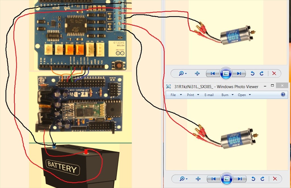
Hello all
Can I properly hook up an Arduino Motor Sheild to EZ-B, to run 2 DC motors.
If so, can I get some sort of diagram/schematic? I need to be able to control the speed and direction if both motors individually. Sorry, noob question.


ARC Pro

Upgrade to ARC Pro

Your robot can be more than a simple automated machine with the power of ARC Pro!

Ecuador
#6  
I think that yes! You can use it, but I not Recommend you to do that , better if you can get an H-Bridge.
#7  
@doombot if everything is labeled the answer is yes you can , follow the labeling. The ezb version 3 , the most recent version that was available to purchase was made to accept standard arduino shields. There is a shield compatibility chart I posted a while back too if you search for it or look under my profile of threads posted.
#8  
Really? Why don't you recommend? I wanna know:)
I've seen applications where people use the digital out directly to run motors, just using a transistor and a diode. Can a motor controller be bypassed then using this method?
#9  
Additional info like what motors do you plan to use with the shield, operational voltage and amperage numbers that the motors require.
#10  
Just regular toy DC motors, not sure what the amps are
#11  
Without the dc voltage of the motors nor the power requirements to operate them I can't recommend that you use the Arduino Shield or even an H-bridge.
United Kingdom
#12  
For a few bucks you can get the 2.5A H-Bridge which is most popular and has very detailed tutorials on usage with the EZ-B. Provided your motors don't draw more than 2.5A combined. You will need to know the current draw of the motors, without it you risk buying the wrong parts and possibly damaging them.

If you are dead set on using the shield you will need to find the schematic. Looking at the image you posted for it, there are connections that probably aren't required.

The connections are described here. Basically put, the EZ-B makes things easy so you just need to connect up the digital pins (3, 8, 9, 11, 12 & 13) to any of the EZ-B's D0-D19 ports, analogue (if you want current monitor) to the analogue ports, your Vin to Vin, Ground to ground and set it all up in ARC according to the digital ports used for the specific function.

Bear in mind that the shield is 2A per channel or 4A max. Make sure your motors don't need to draw more than that.
#14  
@Rich thanks dude, I think I got it. I'll play with it a bit.
#15  
After I saw this thread, my inner child kick in and was curious. I had an R/C car laying around along with Arduino and Arduino motor shield collecting dust. So I decided to give it a go. Yes it is possible, wire connection are very similar to the L298N H-bridge.
#17  
@PJ - post a schematic or photos of what you did!
@jstarne - I thought I did? I credited Rich
#18  
Custom H--bridge
PWM D14 Orange ( arduino pin 11 & 3)
D12 ( arduino pin 12) black
D13 ( arduino pin 9) red
D11 ( arduino pin 11) green
D10 (arduino pin 13) blue


User-inserted image


User-inserted image
#20  
It's hard to tell the picture, but the diagram should help.
#21  
Thanks PJ! Exactly what I needed...
However if I separated PWM 3 and 11 on respective digital pins I should be able to control the speed of the motors right? I see you tied them together...
United Kingdom
#22  
I would say that you should separate the PWM anyway since this will make the motor move, the dir will determine the direction. So if you only wanted one motor to move you couldn't do that with combined PWM.

The brake may not be required too. It would stop the motor but just shutting off the PWM (setting to 0) would allow it to freewheel which in my opinion would be better if being used for movement.

P.S. It's still showing unresolved this end too, not that it's a problem:)
#23  
Ok Ill try it again...Thanks Rich and PJ!:D
United Kingdom
#24  
In ARC, to make the motor move;

PWM control for whichever digital port you connect to PWMa
PWM control for whichever digital port you connect to PWMb
Set Digital for whichever digital port you connect to DIRa
Set Digital for whichever digital port you connect to DIRb

So, if you chose D8 to D11

PWMA to D8
PWMB to D9
DIRA to D10
DIRB to D11

In your custom movement panel, to move both forwards use the code;

Code:


PWM(D8,100)
PWM(D9,100)
SET(D10, on)
SET(D11, on)


For reverse

Code:


PWM(D8,100)
PWM(D9,100)
SET(D10, off)
SET(D11, off)


For stop

Code:


PWM(D8,0)
PWM(D9,0)
SET(D10, off)
SET(D11, off)


For left

Code:


PWM(D8,100)
PWM(D9,100)
SET(D10, on)
SET(D11, off)


For right

Code:


PWM(D8,100)
PWM(D9,100)
SET(D10, off)
SET(D11, on)
#25  
Yes Separating them is more effective, kinda just threw a quick visual together for you.