
Asked
— Edited
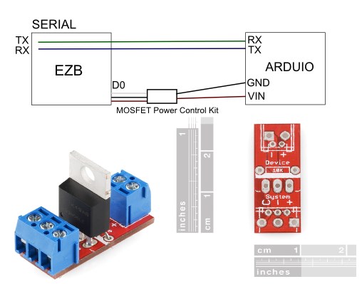
Arduino Mega Is Being Powered Through The Uart Serial Tx/Rx Connection
So I want to control the Arduino power using this RFP30N06LE MOSFET and that works as expected when hooked up to EZ-B D0. However, if the serial TX/RX is connected to the Arduino it get's power via the serial lines bypassing the D0 MOSFET. Any comments / ideas on controlling power and having Serial TX/RX lines connected?

Don't know that much about the Ardunio but TTL/com is normally gnd and (+)3 vdc. Is there something that can be turned off on the Arduino ports ?
Are you controlling the gnd with the mosfet? Sounds like it - because generally any port on any micro when it's closed low will gnd the ic and power it.
If you can control the vcc instead, it'll be good to go
Ya what DJ said...
Okay guys thanks so far. I can not resolve this problem; it is out of my scope of knowledge. If any one could help me that would nice.
I have an Arduino hooked up to the ez-b using serial tx/rx lines. I want to control it power with this device:
MOSFET
Here is how I hooked it up and it does not work. As the EZ-B supplies power to Arduino regardless is D0 is high or low.
If I removed the serial lines then the mosfet works perfectly and can control the power of the Arduino.
I then tried what I thought was DJ's advice and removed gnd from output and the input from the mosfet and the power is still being supplied. Just not sure how to control the power to the Arduino with the serial lines connected.
Do you have a multimeter? Can you check the voltage of the RX and TX lines from the EZB?
I am sure this isn't the case but your wiring diagram scared me a little, the red wire from the EZ-B seems to be connected to GND on the Arduino (through the MOSFET board).
It should be red wire (Vin) power from the ez-b to the '+' on the MOSFET board and the output '+' on the MOSFET board to Vin of the Mega.
The other wire, the black one, should be connected to GND from the ez-b to the '-' on the MOSFET board and the output '-' on the MOSFET board to GND of the Mega.
When a high (3.3V) signal from the ez-b D0 goes to the 'C' on the MOSFET board this will turn it the Mega On and a low (0V) signal from D0 should turn it off.
I should ask if the 10K pull down resistor is installed? This will ensure the N-channel MOSFET is turned off by default.
If all the wiring is correct and the Mega is still staying on, then try removing the wire between rx on the ez-b and tx to the Mega. I'm guessing you don't need bidriectional communication between the ez-B and Mega but rather you are running the Mega as a slave, correct?
Dang it, sorry for the diagram. Here is the updated one.
I have the mosfet connected as you suggested. This is the condition I described above with the described results.
Yes, I have the resistor installed.
If only the Arduino TX and EZB RX are connected the issue seems to be resolved.
Although, I need Bi-directional communication between the two.
Well, I think I may have ruined my EZB. I can no longer connect to it. The blue light flashes and I can connect to it in windows but ARC won't connect and it no longer dings when I power it up. Other then that the light flashes normally.
Is it possibly I could have short circuited by accidentally switch the serial tx/rx lines?