
Uberizer
Hey all, Let me start by saying I'm brand new to the forum. Don't even own an EZ-B product of any kind yet. I just picked up an I-Cybie from the 2nd hand store on the weekend and hacked an external battery into place temporarily on a home made extension cable so I could test his functions. He was fully operational, at least all motors moved as expected. I immediately thought how awesome it would be if this dog could recognize my kids faces and call them by name. I have been considering many options from Rasp Pi to Arduino (my only programming experience so far), to combining the two, etc. The EZ-B seems like the best solution, but I am hesitant to commit to EZ-B because I hate the idea that the robot is tied to my PC in order to do high end processing. I want my kids to be able to bring the robot to family gatherings and friends houses.
So here's my first question. Does the android app have the exact same functionality as the windows app? What i mean is, if I had a camera hooked up can an android phone do all the facial recognition and speech recognition types of functions?
If so, I'm thinking of building a "pet carrier" which hides the phone, does wireless charging, etc. Just an idea I'm toying with. The carrier/charger can then be transported with the dog easily.
I know the space on board the I-Cybie is very limited but I do think this can be done if the EZ-B is removed from the white case it comes in.
I've got a lot of reading to do ahead of me looking at other peoples projects but would really appreciate some pointers in the right directions.
I think I know how to solve the servo issues Steve G had in this thread: https://synthiam.com/Community/Questions/8953 so that I can re-use the existing legs instead of replacing them, and I have already disassembled my dog and done some exploratory modifications. I'll post back here once I've attempted hacking one of the legs the way I plan to so I can tell people if it worked as planned.
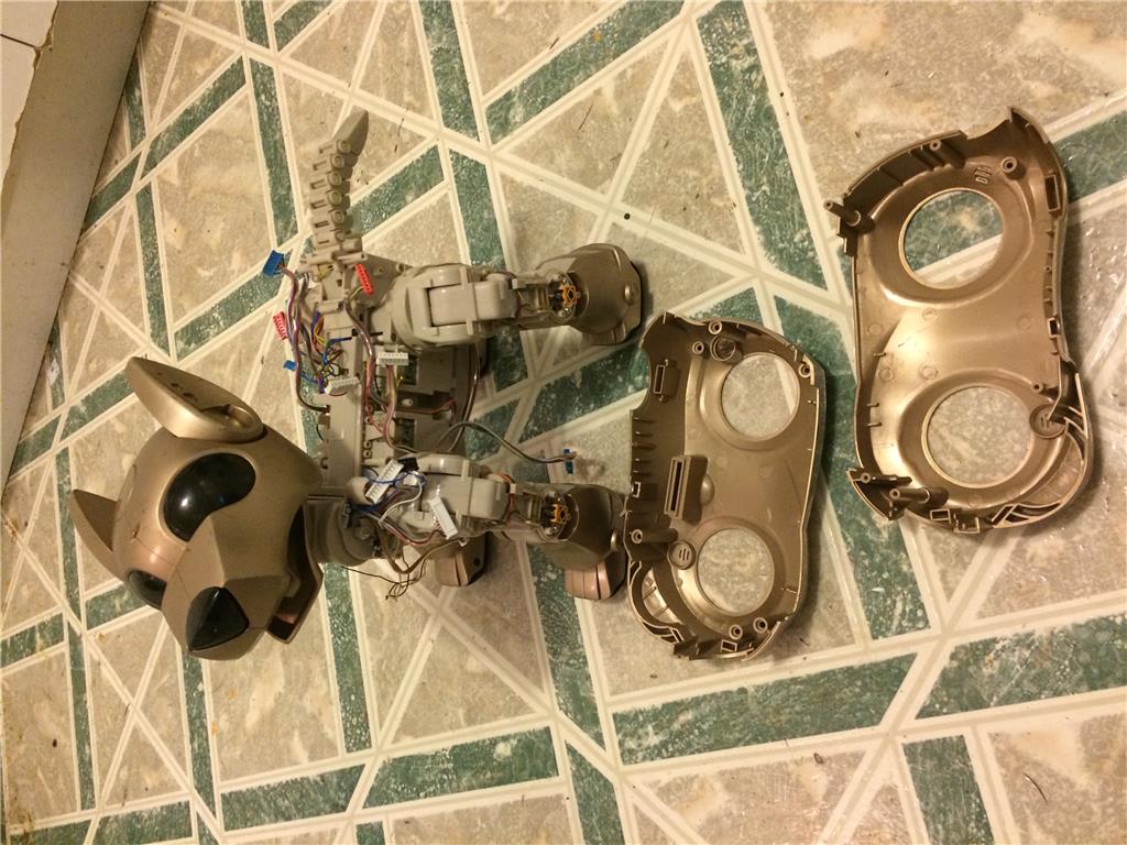
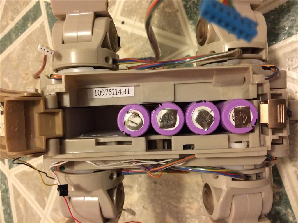
Done so far: -Initial exploratory surgery -widen the battery box to accept 18650 Lithium cells. (4 x 2000 mah set up in 2s2p configuration) in other words 7.4v 4000mah -Hacked an existing hobby servo to do some testing -Removed main body shell and modified to accept slightly wider internals -Gained a lot of admiration for this great little robot.
This dog was designed to be child proof. Every gear motor on this dog has a spring loaded slip gear in it. Some of the motors sound awful when you force them but it's just the spring loaded gear. The dog had a self reset routine it went through when I first powered it up, lying on it's side while it positioned it's legs jamming them up against each other to reset their position. Kind of like a human popping their dislocated shoulder back into place. It was extremely well engineered but they just fell short on the software side.
Can somebody comment on what to expect from EZ-B? Can I have my kids give voice commands? Dog recognizes their faces? Dog speaks to them? Follows them by camera?
The ears are currently fixed solidly in place but if I can find room I'd like to make them rotate forward and backward with a micro servo or possibly move the mouth or both. Currently the mouth opens by moving the head back past a certain angle where the lower jaw stops and the head keeps going. I have a small advantage in making parts in that I have a 3D printer so it shouldn't be too hard.

You should get the IoTiny because it's smaller. Looks like a fun project!
I just looked it up. I remember looking at it before but ruling it out as it says there are only 8 servo control plugs on-board. This dog has 16 "servos" built in and I want to possibly add 2 more for 18 total.
On a side note. Just confirming my idea works! I just did a successful test on one of the robot leg motors and it is now a servo! I did 3 videos 30 sec each of the test setup. I'm psyched! It is definitely possible to re-use his legs.
On a side note, Wowwee robots use the same kind of setup for many of their motors. Zoomer also has a similar setup but probably would not be quite as plug and play. You'd have to trick the servo VR's to allow the wheels to keep spinning once they "reached their positions."
Ok, Here's a couple videos of testing.
For reference purpose, standard servo's are intended to run between 4.5v - 6v. The motors in this robot were originally running at 12V. This would mean a reduction to half speed if I am forced to use 6v to power them. That would hardly be ideal.
The first thing I needed to do was test the board I pulled out of my servo to figure out what it was capable of handling. I started with 3.7v then 7.4v then 11.1v then 14.8v. That was when I finally blew something! A few components on the board lit up orange and let out their smoke. Having said that, the board still works and is the one being used in these videos. However, the motor pushes much weaker when moving forward. It's ok. It was a necessary sacrifice. I now know the servo's can handle 11.1V which would still be almost full speed. I just don't know what the EZ-B will handle. Does anyone know?
You might still get away with using the ezb4 by stripping off the plastic shell... However you will need to find a way to protect the board from making contact with anything metal so as to not damage the board... Also you will need to get creative with powering the board either by using a mini deans connector or soldering power leads directly to the ezb4 board...
https://synthiam.com/Tutorials/Files/EZ-Bv4%20Datasheet.pdf
This will tell you what the v4 will handle voltage wise.
Thanks a lot, that's a great reference! It even gives me the board size without the plastic enclosure, which is super helpful. I'm pretty confident I could shoehorn the EZ-B in there without too much trouble.
I'm holding back right now because it's going to be an expensive project for me. Just an EZB and camera with shipping will cost me $221.90 CAD. I don't really want to spend that much for just these components so I'm still looking at other options like Arduino. Regardless I will still document how to wire up the legs even if I don't go with the EZ-B, just in case it's helpful to someone else down the road.
Ok, a little update. I have finished wiring up one leg and have confirmed the wiring is the same for all 4 legs and the pinout is in the same order on all the plugs. Let me preface this post by saying I don't like the name (angle angle) I used below but my mind is coming up blank on a better name for that joint. Please suggest alternative names.
Color assignment is as follows: Black - Shared 1st contact for both motors power supply Yellow - 2nd contact for knee joint Red - 2nd contact for shoulder (angle angle?) as opposed to (rotation angle) Brown - Variable Resistor outer pin 1 (shared between both VR's) Green - Knee joint VR voltage output (center contact) White - Variable Resistor outer pin 2 (shared between both VR's) Blue - Angle Angle joint VR voltage output (center contact)
Notice the black wire is shared? That's a problem for us. If we leave it that way we could inadvertently set both voltage and ground to the same pin blowing up one of the servo control boards or at the very least cancelling out the movement were trying to achieve. The motors can't share a connection for our purposes. I dealt with this by de-soldering the black wire going down to the knee motor from the little power distribution board at the front of the shoulder and soldering a separate wire to the black wire (use heat shrink). I used the green wire from a USB cable with a damaged plug. Note: it has to be a higher current cable or the wire wont be thick enough. if you open the (angle angle) as wide as possible it's super easy to feed an extra wire through the joint. I didn't attempt to feed it through the clear tubing all the wires go through as I value my sanity.
You will need a servo board per joint so 2 boards for this. I'll post a wiring diagram for this later as I'm running out of time for now.
Ok, so I finished rewiring the left side of my dog. He now has 6 servo boards wired to the six motors that control his left legs. As an added bonus they all work!
If you wire up the potentiometer connections and then solder the two motor wires you can connect the motor to a servo tester and try moving the servo. If it doesnt react as expected you likely have the motor connections backward. Just reverse the wires and re-test.
I have exhausted my supply of servos but have more on the way from HobbyKing. I have an I2C servo board on the way as well to connect to my arduino. Once I have a successful test of all functions I'll stop posting updates. I'd love to see someone else do the EZ-Robot method once I've shown how to convert the motors to servos.
As you can see in the below picture, I have 2 sets of 2 boards stacked laterally and one set stacked rotated 90 degrees. The boards are all located between the front and hind legs so I leave the area on top for the controller and any other items I think belong there.
The next image shows the space on top I'm talking about.
The next image is just to show that the boards do fit in there with the original body casing in place. It barely fits, but it fits. In hindsight I should have chopped the factory wiring much shorter and will have to go back and fix it as I suspect it will be hard to bunch it in there and yet still allow free rotation of the legs on their hip sockets.
One final note, I just realized the side body panels can be installed and removed without removing the legs from the body if you just take off all of the gold leg coverings. The hole is large enough to pass over the leg without issue. Wish I'd realized that at the beginning as it was difficult to pry the body panel back far enough to get onto the 4 leg screws.