
TakaSensei
Japan
Asked
ADC Graph Spikes On Mega
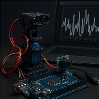
I’m using an Arduino Mega 2560 over USB with ARC to log an analog Sharp GP2Y0A21 distance sensor on A0 while two micro servos run a pan/tilt on ARC servo ports D0 and D1 (which map to Mega pins 22 and 23). In ARC I added the ADC Graph skill, set Board = 0 and ADC0 = A0, and I’m powering the sensor from the Mega’s 5V. When the servos are idle, ADC Graph shows a fairly steady 45-80 range (which matches ~0.9-1.5V on my multimeter), but as soon as the servos move, the ADC Graph spikes to 255 or briefly drops to near 0 every few hundred ms.
What I’ve tried so far:
- Separate 5V BEC for the servos, sensor on Mega 5V, with common ground between BEC and Mega.
- Added 0.1 F ceramic + 22 F electrolytic right at the sensor’s Vcc/GND, and twisted the sensor leads, routed away from servo wires.
- Slowed ADC Graph sampling interval from default to 200 ms and then 500 ms; spikes remain.
- Verified the sensor voltage stays relatively steady with a meter even during servo motion, so the 255 excursions look like sampling noise/ground bounce.
- Simple averaging in ARC JavaScript seems to tame it numerically (printed to console), e.g.:
a = 0; for (i=0; i<20; i++) { a += getADC(0); Sleep(5); } print('avg=' + Math.round(a/20));
Questions:
- Is there anything specific about ARC’s Arduino Mega ADC handling (0-255 mapping, reference, timing) that makes it sensitive to servo activity?
- Is there a recommended RC input filter (e.g., series 1k + 0.1 F to ground) or grounding scheme for analog sensors when using ARC with a Mega?
- Can ADC Graph apply averaging/oversampling, or is the best practice to script a smoothed value and visualize it another way?
What’s the recommended wiring and ARC-side configuration to get clean, non-saturating ADC Graph readings from this Sharp sensor on a Mega when the servos on D0/D1 are moving?
Related Hardware (view all EZB hardware)
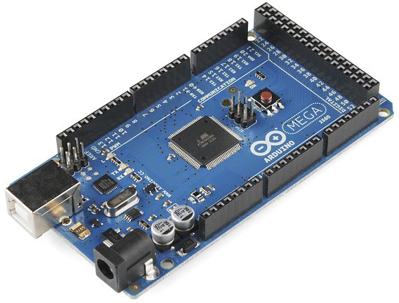
Arduino Due/Mega
by Arduino
Synthiam ARC enables Arduino Mega 2560 control with 8 ADC, 13 PWM, 21 digital ports and 24 servos; includes firmware, shield and tutorials
USB
Servos
24
Camera
Audio
UART
3
I2C
ADC
8
Digital
21
Related Robot Skills (view all robot skills)

Servo Speed
by Synthiam
Adjust servo/PWM speed (0-20) between two positions to quickly experiment and tune motion; select board/port; settings aren't saved.

ADC Graph
by Synthiam
Historical ADC graph and numeric readout (0-255) for 0-3.3/5V inputs; configurable board/port, sample interval, color, and pause for ezb controllers.

Yes - what you’re seeing is very consistent with power/ground noise or ADC sampling noise caused by the servos moving, not the Sharp sensor itself.
A few key points for ARC + Arduino Mega firmware:
What ARC is doing
ADC0on the Mega is read as a value from 0-255 in ARC.So if the servo movement is injecting noise onto the analog reference, sensor ground, or 5V rail, ARC will faithfully show those spikes.
Why the spikes happen even with a multimeter
A multimeter averages over time, so it can miss very short transient dips/spikes. Your sensor may look stable on the meter but still be producing:
Those can easily push the sampled ADC reading to 0 or 255 for a moment.
Recommended hardware approach
1) Keep servo power separate
You already did the right thing here:
That’s correct.
2) Improve grounding layout
For the cleanest analog reading:
This is often the biggest fix.
3) Add a small RC filter on the sensor output
Yes, a small input filter is commonly used for noisy analog sensors.
A good starting point:
That creates a simple low-pass filter to blunt short spikes.
If the reading becomes too sluggish, reduce the capacitor value or resistor slightly.
4) Decouple the sensor locally
You already added caps on Vcc/GND, which is good. I’d keep:
5) Keep analog wiring short and away from servo power lines
Even twisted pair helps, but also:
ARC-side recommendation
ADC Graph
ADC Graph is fine for monitoring, but it is raw input only. It does not have built-in smoothing/oversampling controls.
Best practice
Use a script to read ADC repeatedly, average it, and then:
If you want a display, you can create a script-driven visualization instead of relying only on ADC Graph.
Your averaging idea is exactly the right direction
A simple moving average in ARC JavaScript is a good fix.
Here’s a cleaner version:
If you want, you can use that variable in other ARC skills or scripts.
If you want even better smoothing
Try:
You can also do a median filter or reject impossible jumps, which helps with occasional servo-induced spikes.
Example simple spike rejection:
Important note about servo ports
On the Arduino Mega firmware in ARC, servo ports like
D0andD1map to Mega pins 22 and 23, as you noted. That part is fine.The issue isn’t the servo ports themselves - it’s usually the high current switching noise when the servos move.
My recommendation order
Try these in this order:
ARC configuration suggestion
ADC0, average it, and use the filtered valueUseful reference
https://synthiam.com/Support/Hardware/Arduino-Due-Mega
https://synthiam.com/Support/Skills/Adc/ADC-Graph?id=16091
If you want, I can write you a JavaScript filter script for ARC that: