
2S Lipo Battery Monitor
As also posted in my Hearoid showcase topic, but useful for anyone running LiPo batteries (could be adapted easily for 3S and 4S without too much of a problem).
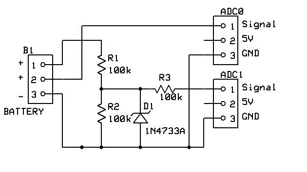
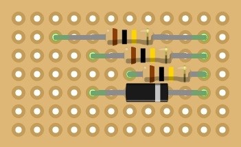
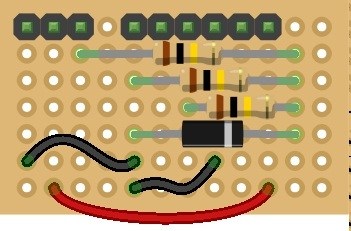
Parts needed: 1 x Zener Diode 5.1v 500mA (Farnell ref 1861447) 3 x 100k ohm Resistors (Farnell ref 9339078) 1 x Small Piece of Strip Board (12 strips x 7 rows) - Maplin FL17T 3 x Pin Header (1x3) or 1 x Pin Header (1x3) and 1 x Pin Header (1x6) eBay Search 1 x servo Extensions (male to male) - made from 2 normal ones cut & soldered. Solder Soldering Iron Cutters
The Schematic:
Method:
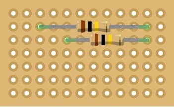
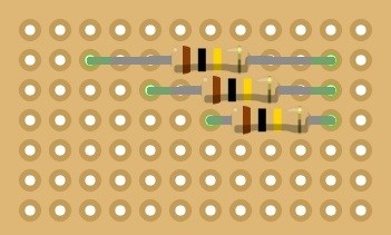
Solder R1 - 100k resistor from Row 2 Column 3 to Row 2 Column 11

Solder R2 - 100k resistor from Row 3 Column 5 to Row 3 Column 11
Solder R2 - 100k resistor from Row 4 Column 7 to Row 4 Column 11
Solder D1 - Zener Diode from Row 5 Column 5 to Row 5 Column 11 (Band to the right)
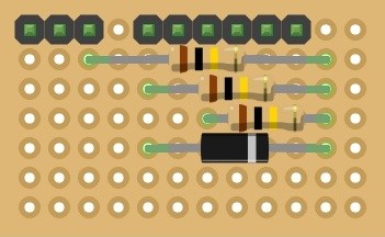
Solder the pin headers on Row 1 Columns 1, 2, 3, 5, 6, 7, 8, 9 & 10
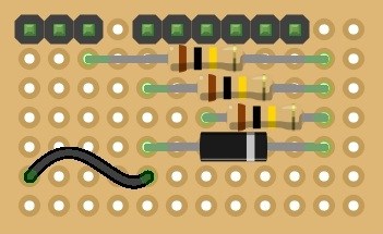
Solder some black off cuts of wire from Row 6 Column 1 to Row 6 Column 5 and from Row 7 Column 5 to Row 6 Column 8
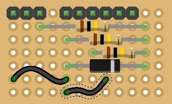
Solder an off cut of red wire from Row 7 Column 2 to Row 7 Column 10
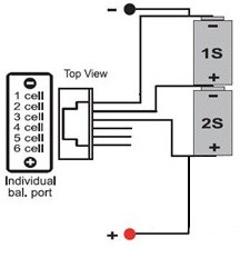
You're all done. Plug the balance port connector in to the 3 pin header on Row 1 Columns 1 to 3 (Ground to the left) and plug in some servo extensions (male to male) or 3 pin JST to servo on the two other headers (Ground on left on both), connect the other ends to ADC0 and ADC1 (or any other two ports if those are taken but you will need to adjust the script below if you do).
Now, to use the information in ARC...
The EZ Script
# Read voltage level of 2S LiPo battery and report to software.
# Set variables
# Change $vundervoltage to the under voltage of your specific battery (leave at 3v if unsure)
# Change $vcritical to your lowest voltage you wish for the battery to get before human intervention
# Change $vmin to low level alert value
# Change $vmax to battery full charge
# Change $multiplyer if using voltage divider
# Factor is 5/255 for adc value conversion to volts
$vundervoltage = 3
$vcritical = 3.5
$vmin = 3.7
$vmax = 4.5
$multiplier = 2
$factor = 0.019607843

:ReadCells
# Get ADC values
$vc1 = GetADC(ADC0)
$vc2 = GetADC(ADC1)

# Convert values to voltage
$cell2 = $vc1 * $factor
$cell1 = $vc2 * $factor * $multiplier
$cell1 = $cell1 - $cell2
$batteryv = $cell1 + $cell2

# Check for errors on circuit
IF ($cell1 > $vmax or $cell2 > $vmax)
  Print("Battery Monitor Error")
  Print("Check Monitor Circuits")

  # Check for errors on battery connection
ELSEIF ($cell1 <= 0 or $cell2 <= 0)
  Print ("Battery Connection Error")
  Print("Check Battery Connection")

  # Check for under voltage
ELSEIF ($cell1 <= $vundervoltage or $cell2 <= $undervoltage)
  Print ("Battery Under Voltage")
  Print("Check Or Replace Battery")

  # Check if at critical levels
  # Cell 1
ELSEIF ($cell1 <= $vcritical)
  # Do sometihing if critical
  Print("Cell 1 Critical")
  # Shut down all power, switch to back up battery alarm?

  # Cell 2
ELSEIF ($cell2 <= $vcritical)
  # Do sometihing if critical
  Print("Cell 2 Critical")
  # Shut down all power, switch to back up battery alarm?

  # Check if below recommended levels
  # Cell 1
ELSEIF ($cell1 < $vmin)
  # Do sometihing if voltage low
  Print("Cell 1 Low")

  # Cell 2
ELSEIF ($cell2 < $vmin)
  # Do sometihing if voltage low
  Print("Cell 2 Low")

ELSE
  # Output voltages
  Print("C1 Round($cell1,2)V")
  Print("C2 Round($cell2,2)V")
  Print("To Round($batteryv,2)V")
ENDIF
# Wait 5 seconds
Sleep(5000)

# Go back to the start
Goto(ReadCells)
Note: The should be just a normal closed bracket ) but the forums tend to think otherwise.
Update: Refer to page #2 post #18 for updated code taking in to account the updated syntax

Hi Rich,
Today I found my Lipo Turnigy 2S 3000mAh dead with the 2cells measured at 1V (Wall-E stayed "on" all day long). So I think I need to build a monitor to shut down the robot when it is critical...
So I am going to follow your tutorial, but I need all the parts (and I have no electronic shop near home). Could you give me a link to a site (ebay or e-shop) where I can buy all the parts needed?
PS: I have found some ebay links but part references are not exactly the same as in your tutorial and I don't want to buy the wrong Zener diode or resistor.
Thanks in advance
I use farnell, they are worldwide so you should be ok with them in France. www.farnell.com They have a minimum order value but I have managed to fill it on all orders so far.
I need to revisit this circuit, I finally managed to test it today but it isn't reporting the correct voltages. I think it may be the diode but I cannot be certain, it may be where I'm using 100k resistors and before I was only using 10k.
I'll edit the first post with part numbers from Farnell.
Thanks a lot.
Don't hesitate to make an update if you modify the circuit. As I am really new to electronic, I am going to follow your tutorial blindly... more or less.
Thanks for part numbers... do you have any for a simple Strip Board and for Pin Headers? I found around 1800 & 8000 references on Farnell site... I am a little lost.
OK, figured out the problem, the diode is causing the circuit to give false readings.
I've removed it on my circuit, it is there for over voltage protection (so if R2 open circuits it could send the full 8V+ in to the ADC port).
I need to try it directly across R2 but if you aren't worried about over voltage (and to be honest, I fed 8v in to my adc and it took it without any smoke but don't count that as a guarantee) build it without the diode.
I got my stripboard and pin headers on ebay. I've no idea on any codes or anything
Ok Rich. Thanks for all the infos.
Sorted it, just changing the first post.
The diode is in the wrong place and gives incorrect readings where I originally put it. Directly across R2 gives correct readings and over voltage protection.
Updated the original post.