
2.5 Am Motor Controller. Blue Smoke Question . :(
After modifying the G-Bot's power supply to adequately power his neon transformer I decided to change the input voltage for the G-bots arms and bubble lifter to increase their respective speed. The motors and actuator I'm using for the arms and bubble lifter are all rated up to 48 volts so I thought I was safe.
I had searched and searched for specifications for the EZ Robot 2.5 amp motor controller since I had a few of them on hand. I finally gave up after not finding specs and decided to just go ahead since I did find specs for the L298 chip online which showed input voltage up to 48 volts...
Well, when testing the arm motion, a LOUD crack rang out from the controller followed by the dreaded blue smoke.... 
I guess I just need to know if the input voltage of 24 volts was definitely responsible? I've checked more than once and can't come up with another reason...
Is there a specification sheet out there specifically for the EZ Robot controller?
Can anyone suggest a different controller I could use with the EZB v3 to controller the arm motors with a 24 volt input?
Thanks
Gwen

Sabertooth 2 x 12 (up to 24v) or sabertooth 2 x 25 (up to 30V)....
that 2.5amp h-bridge is meant for little toys that don't weigh much... It's a wonder you didn't light the poor thing on fire....
24v should be fine on the L298n controller, provided it's connected to Vcc not +5V.
Current may be the problem. What is the current draw of the motor you were testing?
Do you know what went pop and released it's smoke? Was it the on board voltage regulator or the L298n chip or maybe something else?
I have operated an L298 at 24VDC in the past with success.
I agree with Rich that current handling may have been the issue, what kind of motor were you driving? If it was moving an arm I'm guessing it was drawing a lot of current.
Well, I actually may have smoked two of the 2.4 amp L298 controllers.. Not really sure yet.
I wanted to use one to control a linear actuator to act as the G-Bot's bubble lifter. That is the one I was asking about (in another post) how to control one motor using only two EZB ports since the linear actuator only needs full on or full off and I'm using a lot of the EZB ports already. I was messing with the script commands to do that: Joystick Button (to control bubble lifter down action) down:
Button up:
Joystick button(to control bubble lifter up action) down:
Button up
I was fiddling with which two pins on the controller controlled which motor out since I wasn't sure if I had the actuator connected to the correct side on the controller. I was only able to get the actuator to work once. No POP but I vaguely smelled smoke and could not get it to work again.
Sooo, I decided to try out the other controller (I already had installed to work both arms but had increased the input voltage to 24 volts to get more speed out of them.) I connected one motor and activated it. The arm extended then POP! the controller made a loud cry and smoked... Mind you this controller worked perfectly and was wired exactly the same as I had it before except that I changed the input voltage to 24 volts.
I'm wondering if BOTH the actuator and the arm motors drew too much current or whether the voltage is responsible for them both frying?
Unfortunately I don't have specs on either the linear actuator or the arm motors. I bought them both as surplus many years ago... AND unfortunately I do not have an amp meter so I'm kind of living on the edge here.
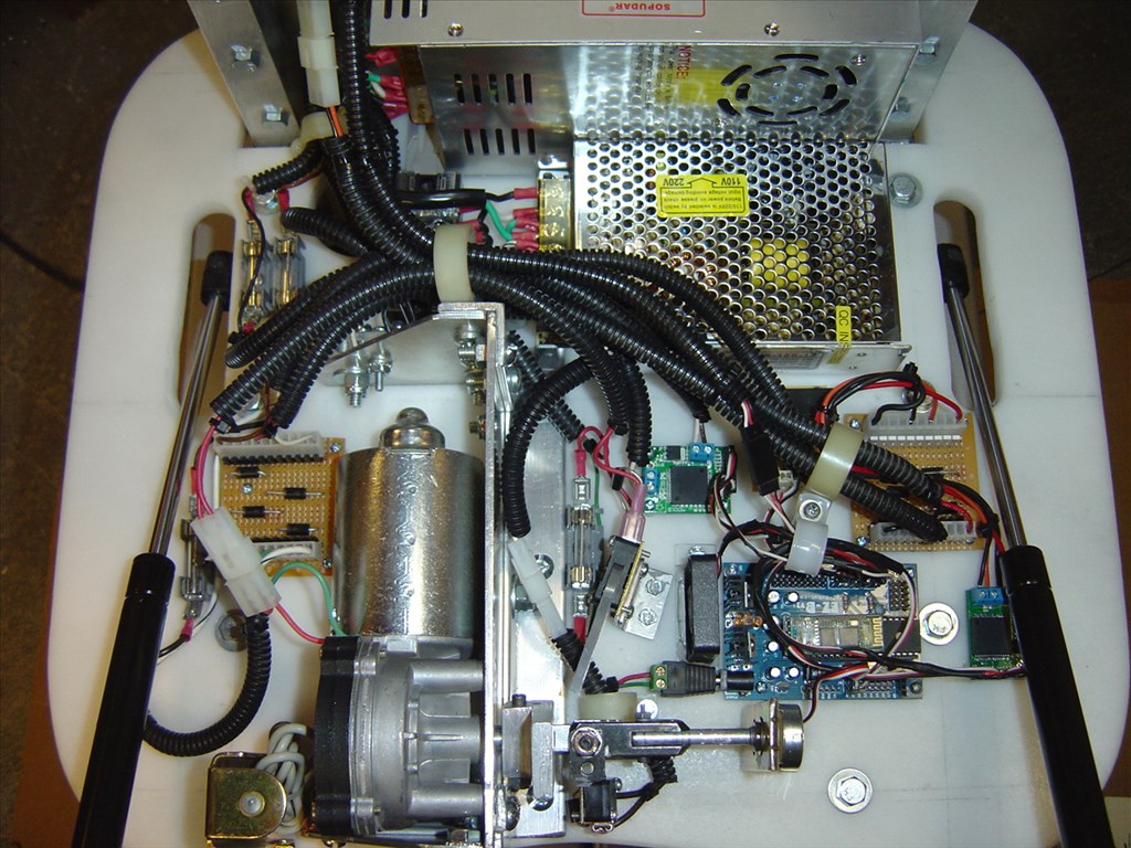
I've attached a couple pictures of one of the arm mechanisms. It is really set up for robotic control. They have three stepper motors on them all with position resolvers. I was only trying to utilize one of the motors for now to extend and retract each arm. I'm thinking when the arm fully extended it just drew lots of current because it didn't turn off when it reached its limit. Its a shame since all three motors have resolvers on them and I just do not know how to utilize them - pity.
Should I be able to use the resolver on the motor I'm trying to use to feed a signal to the EZB and have script turn it off when it reaches its limit of travel? How would I know which wires on the resolver to use or how to wire it? The resolver connectors have four wires (red, black, green and white).
Gawd, so frustrating operating beyond my scope here...
Also, each of the arm motors have four power connectors. two each labeled 'A' and 'B'. I had connected the two 'A's together and connected to ground and the two 'B's and connected them to power (12 then 24 volts). That seemed to work to extend and retract the arms but the movement was slow with 12 volts. I thought upping the voltage might speed them up(and it did briefly before the 'event' but now I'm wondering if steppers can even be used like this? Should I just be using one 'A' and one 'B' on each motor?
It has all just been trial trial and error so far. Its kind of a wonder I hadn't produced the dreaded blue smoke long before last night...
As usual, all comments and suggestions are appreciated...
Gwen
Gwen, I have the same motors. I was also going to use these for my B9 arms but decided to avoid using them because of the weight and they seemed overwhelmingly complicated. My hats off to you for trying. Have you thought about contacting the guy that sold these? When I bought mine he mentioned having to do a few mods to get them to work properly. His name is Dennis and I have his email address. Let me know if you want it and I'll get it to you. Here's a link to a web site showing these motors being used for B9 arms:
In Neon - Building the LIS Robot
I think the extra set of lugs on that motor is for a break. I bet you applied voltage to both the break and the drive motor. I'm guessing the break was clamped down while the motor was trying to move. That would make the current spike while it was trying to move.
Good luck, Dave
Gwen, I can't help you with those motor connections... however, I can recommend a tool for your workshop. This is has been a really useful tool for robotics in my experience: https://www.ebay.com/itm/30V-10A-10AMP-110-220V-Precision-Variable-DC-Power-Supply-Pro-Digital-Adjustable-/361010437468?pt=LH_DefaultDomain_0&hash=item540de61d5c#ht_6411wt_1263
The adjustable power supply allows you to control the voltage and monitor the amperage. It is extra convenient for situations similar to yours - experimenting.
Without knowing much about those motors and the mechanism, a tool like the variable power supply will allow you to slowly increase the voltage and monitor the amperage to better understand your current requirements.
Thanks for all the suggestions guys.
Dave, i know Dennis. He lives only a few miles from me here in Massachusetts. I remember when he initially bought these ten years ago. At the time, he was as baffled as i on how to use them.
Havent talked to him in a long while. Ill drop him a line and see what he ended up coming up with.
Thanks!
PS, Still looking for a spec sheet on the EZ Robot 2.5 amp controllers...
Gwen,I don't know the specs on your motors but from looking at your pictures i am pretty sure that these exceed the 2.5 amps that the motor controller can handle.