Affordable Modular ARC Robotics Kit
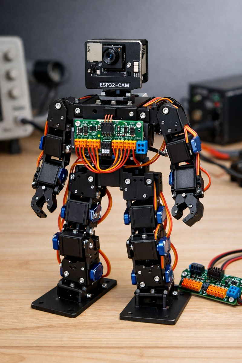
Is it time for a new ARC compatible Robotics Kit? Most of us came across ARC back in the days of EZ-Robot. These are great robotic kits for schools and summer camps to teach kids robotics. The problem is the cost and availability. ARC now works with ESP32-CAM and PCA9685 controllers. Together these provide a lot of the functions of an EZ-B for around $5. So now using low cost servos like MG90S or other 9g servos you can build a bipod robot that works with ARC for under $50. Using a modular design the pieces could also be used to build other robots like Hexapods, Robotic Dogs, Rovers etc. ARC has all the functions built in to support a new robotics kit all we need to do is design the connectable servo casings, servo horns. body and other components for 3D printing. We could then provide the free 3D printable models and even make kits available for sale. ARC makes it easy to program, build and configure the robot and this would make robotics a low cost barrier of entry for students and still teach all the skills needed to learn basic robotics with all the features that now come with AI integration.
There are a bunch of opensource ESP / PCA based robots available that you can make work with ARC today, but I think a modular design that allows you to build a range of different robots that have pre programmed projects, scripts and build instructions available for ARC would be the best approach.
Anyone interested in working on something like this ?

Well if I get it working you will be handed a spaghetti code mess but that’s what hacking someone else’s code is all about. Turns out the touch sensor was a hardware problem because if I short out GPIO 15 to GND ARC says yep so I will just pretend it’s a button for now. The battery and ultrasonic sensor have stumped me and how you get these WS2812 to change colour is beyond me and as for buzzer to do anything but beep but seriously what else is a Canadian gonna do when it’s -20 outside.
BTW you will love the colour coding on the cable for the touch sensor they included. Red is signal black is power and yellow is ground of course. Am I surprised it doesn’t work.
@nink
am tempted to print this humanoid robot . would be a nice challenge .
I’m actually laughing because I know what it’s like to work with that open source hippy code. Someone with very beginner coding skills created a GitHub for an arduino project at some point. China, whos entirely country can’t comprehend code, copied the GitHub and started selling it. That’s usually the lifecycle.
Oh, and when China makes the project popular, the original author gets upset they didn’t get compensated. There’s always that part.
The code also changes a bit as it flows through a game of "telephone". Each time it is repurposed, it has parts hacked away. By the time you’re using it, it’s less than half of the terrible condition it was as original haha.
So yah, I’m laughing that you get to experience what I always complain about on here . I partly feel comforted by it!
@Dj I've been slowly reworking the hexapod GAR on the weekends, but it requires use of 24 servos. I could swear (i saw but since cannot find) a convo with Nink where he asks if you could double up the PCA 9685 on the ESP32 CAM set up. And I think your reply was something like you can't double up to 30 but can make it work for upto 24 servos. Is this as simple as listing boards ie first board is 0x40 board 2, 0x41...or is it more involved code wise? Gar will be the next robot in the Mecha Morphix line. Much lighter resin higher resolution prints and more powerful servos and some light aluminum to make the structure more sound.
Todays update a little busy so didn't look at much. I fixed the ADC battery read problem turns out the PCA9685 Firmware ID I was using didn't support ADC so I just used Firmware ID 5 that I found in the old ARC arduino firmware so now I can read battery status #define _FIRMWARE_ID 0x00000005
@DJ if you get bored can you add Freenove Robot Dog and assign a Firmware ID.
@Will not sure but you should be able to link multiple PCA9685, When you select the ports just choose a different board in dropdown for EZB Type like UNKNOWN EZB where you can just select the port D16 to D23 from there.
This is what I have working so far
D17 Buzzer GPIO33 Uses LEDC (tone)
D20 WS2812 LEDs GPIO0 4 onboard LEDs
ADC6 Battery Detect GPIO32 Shared with TRIG
Camera Working OV2640
PWM Servos D0 - D15 Working
Todo Camera Try an OV5640
D16 Touch Sensor GPIO15 looks like touch sensor broken but I had feedback shorting out GPIO15 and GND
I still can't get Ultransonic sensor working ARC Just disconnects when I un pause sensor. I am wondering if this board is just to underpowered to handle data stream even though I set long wait time. D18 Ultrasonic TRIG GPIO32 (Shared with battery ADC) and D19 Ultrasonic ECHO GPIO12
@ Nink I must be missing something. In the code I clipped above (from DJs firmware) the default I2C address is set 0x40. When you solder on another one, you have to solder A0 closed to have the second board address to 0x41. My understanding is thats the only way to access the other board is to address it as 0x41 in the code.
You are right I took a quick look at the PCA sections of DJ code and we need to create a 0x41 Unfortunately I don't have 2 boards to play with. I blew mine up and have some more on order from China. I just ordered 2 from Amazon Prime so will play tomorrow.
In his code I see defines the port #define PCA9685_ADDR 0x40 Assigns a PWM Driver Adafruit_PWMServoDriver _pca = Adafruit_PWMServoDriver(PCA9685_ADDR); probes to see if active while (!probeI2cAddress(PCA9685_ADDR)) { and prints results Serial.println(); Serial.println("PCA9685 I2C probe failed (no ACK)."); Serial.print("I2C SDA GPIO: "); Serial.println(PCA_SDA_PORT); Serial.print("I2C SCL GPIO: "); Serial.println(PCA_SCL_PORT); Serial.print("PCA9685_ADDR: 0x"); Serial.println(PCA9685_ADDR, HEX);
So I assume we can just define second port #define PCA9685_ADDR_1 0x41 and then assign another PWM Driver Adafruit_PWMServoDriver _pca_1 = Adafruit_PWMServoDriver(PCA9685_ADDR_1); and then just check if active and print PCA9685_ADDR_1,
We are also going to have to map the ports 16 to 23 to PCA9685_ADDR_1 I am not sure if thats the best way to do it or if we would be better off balancing 12 ports on each PCA board.
Here is my latest firmware I have added some GPIO and ADC ports I will try and add a second board tomorrow when it arrives. https://drive.google.com/drive/folders/1oV6LcXC9HRX0IyGwv2OOlL0FZixJousN?usp=sharing