United Kingdom
Asked — Edited

Fun With A Kangaroo/Sabertooth

This is a video to show you guys how good the Kangaroo/Sabertooth motor controller combo is!

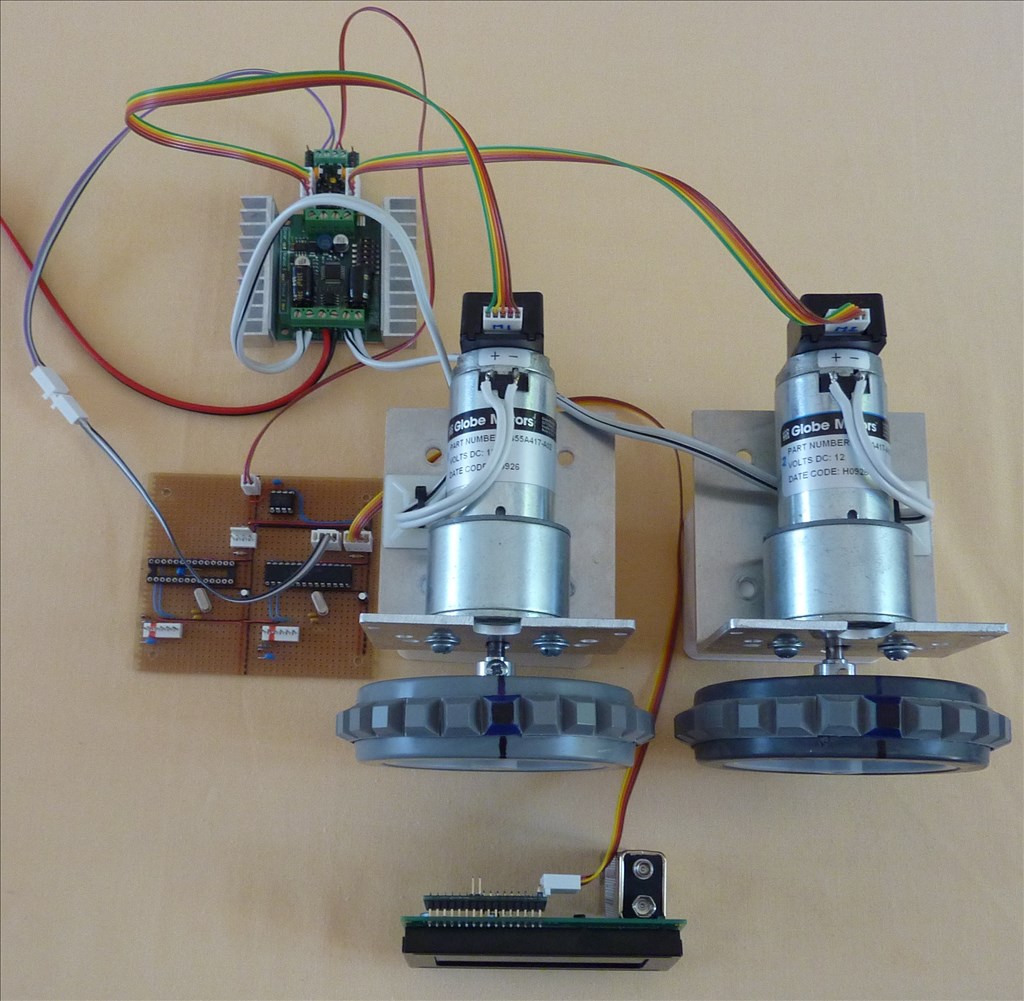
Dave, this video starts by showing the ramp-up - full speed - ramp-down algorithm that I coded on the PIC microcontroller, you will see how GET_POS is read and controls the ramping up/down. The ramp-up and ramp down rates can easily be change via a variable. When I get my V4, I will port the algorithm over to an EZ-B script for those that want it.

The second part is to show you folks how important encoders are, here you can see the incredible synchronising that the Kangaroo's auto-tune PID has. I have sent it precision movement (distance) commands for hours with barely no loss of motor synchronisation which means that you can build a robot that will accurately move in a straight line and move/turn to the exact distances that they have been previously programmed/taught. I use this for accurate room mapping and having pre-learnt routines which enable my robots to move from one room to another or to a particular room location.

User-inserted image


ARC Pro

Upgrade to ARC Pro

Discover the limitless potential of robot programming with Synthiam ARC Pro – where innovation and creativity meet seamlessly.

#1  

@Tony, This is wonderful! I'm so glad you talked me out of ripping out my Kangaroo / Sabertooth and not going back to a regular H-Bridge. You make it look so easy. I fooled around for over a month to get mine to operate even close to what you did in such a short time. I did get my set up to ramp up and down at different speeds and stop at any spot I wanted. However even with useing your precentage suggestion I just couldnt get my script to stop the ramp down the proper way. I even used a pot attached to EZB's ADC ports for feedback to trigger the ramp down script with mixed results. I got flustered and busy with other things around the house and gave up till I got my new EZB. Now that I have the V4 EZB and have two way serial communacation I can use Kanngaroo's Get() function and give it one more try. If I do get it to work I'm sure it will not be as elagent as your script so I'm really looking forward to useing it when you get your V4 and find the time to port it.

Could you tell me how you have the Kangaroo set up? Where do you have the dips? Are you running in Postion or Speed Mode?

By the way, sorry I didnt return your private email last time. Life tends to sweep me away at times. tired

United Kingdom
#2  

That's some great work, you'll have me believing in encoders soon :)

Sabertooth and Kangaroo are certainly being added to my wishlist now! I don't have anything planned for them but I'm sure I'll think of something.

#3  

Yes! This will definitely solve most of my robot challenges if I can get it to work. I was sold with the RC video that dimension put out but your video put it over the top. I just added magnetic encoders to my motors yesterday (tip, don't use a vise to hold a thin ceramic magnet while drilling a larger bore) However, i'm using the v3. I posted this question to Dave in another thread but maybe everyone here will know. I was reading this in the kangaroo manual yesterday:

[i]Enable multi-Kangaroo mode (shared signal lines) When disabled, Kangaroo drives the S2 line high when it is not sending data on it, to give a stronger idle signal. One consequence is that S2 cannot be shared.

When enabled, Kangaroo will only drive S2 when it is sending data, and will enable an internal pullup resistor when it is idle. The idle signal is weaker, but S2 can be daisy-chained between them. [/i ]

would this solve two way with the v3? @Toymaker i'd very much be interested in the v4 script or maybe a control feature on the ez-gui could be added.

Thank you for posting this, it makes me feel better about my project.

United Kingdom
#4  

Yes the EZ-B should be sufficient however it is not natively supported and will require the SendSerial() command to be used. If popularity increases I am sure DJ will add support for it to his list of additions for ARC.

#5  

I am watching this thread with great interest... i could not get the kangaroo to work as Anthony suggested (plug n' play).... Dave I think used a pot for initial set up of the kangaroo leading me to believe at this point (until maybe an update of ARC) you'll need more than the ezb to get the kangaroo up and running...

United Kingdom
#6  

@Lumpy has used the Kangaroo on his R2D2, I was under the impression that it was working fine but I may have missed a post or something.

In theory it should work, it's a serial controlled device which sits between the EZ-B and the Sabertooth. Provided you send the correct serial commands it should work without any problems.

#7  

mdeming1, I don't think your idea will work. EZB needs to receive serial commands to let the two work together. The only way I found around this was to attach a pot to the motor and then ezb's ADC port. That way EZB knows the position of the motor and can interact with EZ scripts in ARC. Of course with pots you are limited to how many rotations you can go.

#8  

You're going to need an encoder or potentiometer as several have noted before.

I bought these and they were quite easy to install, even on my massive motors. I'll report back when I see if they are actually good enough to make the kangaroo work. They only have a ground,5v and signal wire. I do have two unused signals coming from the motor where the brake was however and have a message into dimension about this dilemma now. I note the wire count and uncertainty because you'll note that Tony has the multicolored five wire encoders attached to the rear of his motors going into the kangaroo. Encoders for driving and potentiometers for servo movement I guess is the rule.

https://www.sparkfun.com/products/12629

If you do buy this encoder, each pack has enough for two motors. I didn't know this and bought two packs.

I hope this is a relevant post.

@Toymaker could your (I think those are pic) setup be used alongside a v3 to make up for not having the two way communication? I'd like to see if I can make something like that work on my v3 now if at all possible. edit: or would using two ez -b v3 boards (assuming I could find an inexpensive used one) work for the two way com?

regards

Matt

#9  

Once you get everything running together this setup works great with EZB. My complaint was there is no native speed ramping in position mode. The startup and stop is very quick and the bigger the robot the more unhuman it looks. Plug & Play? Not even close but not to bad once you get everything working together.

#11  

Hi Dave, got ahead of the thread there, sorry.

re: ramping. There are two sections on ramping in the manual:

http://www.dimensionengineering.com/software/DEScribe/html/

I'm sure you saw them but just in case. Have you tried playing with the speed "screw" on the kangaroo itself?

edit: I wonder if splitting the encoder wires between the v3 and kangaroo or having one encoder to each would be a workaround.

Matt

#12  

@mdeming1... Matt, Matt... wishful thinking but the V3 can't read serial no matter how you wire it... You need to use another way... As mentioned before, Dave I think used a POT and Tony used a PIC micro to get the Kangaroo set up

United Kingdom
#13  

The Serial communication on the V3 is one way only, which is send only.

The only other method would be to use some kind of I2C to Serial bridging set up. I don't even know if such a thing exists.

United Kingdom
#14  

It depends what you want it to do.

Feedback input is connected to the Kangaroo X2 as are any limit switches you want to fit. These are required so the Kangaroo knows how fast and how far a motor is moving. This is all taken care of on the Kangaroo.

If you need ARC to know this information too then you need bi-directional serial or use some feedback devices on the EZ-B. As far as I can see this is not a requirement it may just be useful for movement.

It's certainly never been looked at as plug and play since it isn't natively supported by ARC so will need scripts, scripts which may end up being long and complex in some circumstances. However, it will work with the EZ-B sending only, at least the commands to tell it what to do will. The commands to retrieve information from it such as speed or distance etc. will not work with the V3.

It's very likely that you could use an Arduino to bridge the gap and control it through the Arduino via the I2C however this will involve a lot of Arduino coding too. Since the Arduino can receive the data you could connect the Arduino to the EZ-B V3 via I2C, send I2C commands to the Ardunio to control the Kangaroo which then controls the Sabertooth. Not ideal, very long winded but it should work.

United Kingdom
#16  

Dave, I am running the Kangaroo in Position Control mode (DIP 3 on) and also in Mixed mode (DIP 4 off). I control the speed by the "s" (speed) command and use this in my ramping routines. The position mode is good for me as I want very accurate movement from location to location for the robot moving around its environment.

My PIC micro (shown) has an I2C bus interface and can be controlled by a V3 as the I2C from the V3 is bi-directional and the PIC then handles the bi-directional serial to the Kangaroo. But now with the V4, you will not need this as the V4 can talk directly to the Kangaroo via its bi-directional serial port.

I am doing things differently though with the EZ;1 and EZ:2 robots, as I do not want the V4 to be "bogged down" by lower order system functions like locomotion, head control etc. I want the V4 just to issue a command to (say) the locomotion PIC such as "move to kitchen", then the PIC will run the relevant "move_to" pre-learnt routine to take the robot from its current position to the target position is say another room. The PIC also handles all the collision avoidance data coming from my narrow band sonar array (as photo below) and motor stall detectors. It only reports back to the V4 when either it had attained its target position of failed to because of an obstruction etc. By taking the heat off the V4 it enables it to get on with other important functions like vision etc.

If you look at my PIC board, the 8pin IC is an 64K x 8 (512Kbit) EEPROM this holds all the pre-learnt movements and locations library with the positional nodes held in DWORD (4 byte) arrays.

User-inserted image

#17  

@Tony, what you're doing with the Roo/Sabertooth amazes me. Sadly your work with the PIC is way over my head but I do understand the basics of what you're doing. When you describe your theories I feel like Dr McCoy listening to Spock on the bridge of the Enterprise in Star Trek. confused However I'm not going to call you a "green blooded Hobgoblin" though. :D It's all good because the intent comes through and makes sense that way. ;)

I have my dips on the Roo set the same so I should be able to get the same results as you with the proper script now that I have my V4 (hopefully).

One point I'm unsure about is where on the V4 to get the serial feedback from the Roo. I thought it would be read through on of V4 EZB's digital ports. I thought this because we send serial commands through the signal pin of a digital. Now you say it should read serial feedback from the i2c port. confused I guess I need to get this cleared up.

#18  

I have the same question. I posted a thread about it late last night. Per @RobotDoc's suggestion, I bought a i2c to UART converter to read the serial feedback which I'm hoping will accomplish the same function as @Tony PIC. I don't know how to use it but i'm hoping it will do the job. Any thoughts? Conversely, is it very difficult to program a pic to do what yours is doing with the v3? I've never used one.

United Kingdom
#19  

Dave, apologies for any confusion (I am getting old!), the Roo is bi-directional serial connected (not I2c), as I only have a V3 I had to use a PIC to do the conversion from b-directional I2C (from V3) to bi-directional serial for the Roo.

I am using encoder feedback (of position) you will be using potentiometer, but I do think both will require the same coding.

Going back to my original algorithm, first your script needs to know if the move you require is long enough to require ramping as with very short moves ramping becomes irrelevant.

After this you need to compute the "ramping-down" point of the move (say 10 - 20% from the end position).

Now you can use "getp" (get position) to find out where you are in the move this would look like

Serial out = CHN,getp,13 where CHN is channel number (in the case of a single motor this would be 1 or 2)

The above should return the current position and would look like this

Serial in = CHN,p,2500,13 - here the lower case "p" means that the move is not completed

or

Serial in = CHN,P,3000,13 - here the upper case "P" means that the move is completed

If you want ramping down at the end of motion then you need to work with the lowercase "p" as if you wait for the uppercase "P" then its too late as you would have obtained the end target position. So you would start by issuing a position command like

Serial out = CHN,p,3000,13 where 3000 is the position you want to move to

Then you start a loop that continually checks "getp" to see if you have attained the "end less %" that you computed at the start (say) 2500

After every "getp" you need to check the position and exit the loop if it has hit the computed ramp-down position, something like this

If POSITION > 2500 then goto RAMP_DOWN - we use "more than" here because of the latency of reading the serial back we could overshoot the computed value.

I have not covered start ramp-up as that is the easy bit.

Hope this is of some use.

#20  

@Tony,

Getting Old? It seems like what you have going on in your head is a thousand times more fertile than most 20 year olds. ;) The confusion is my fault. I just cant keep up with you. Anyway, I got it all worked out through out the day yesterday and actually got my motor to move by sending a serial command from my V4's UART port to the Kangaroo. It was not controlled or exact but it was a thrill to see it happen. I knew I was on the right track when I sent the "Start" command and saw the little LED on the Roo blink. :D DJ's Example Project on using the UART port and some kindly guidance by forum members really made the difference. I gotta keep reminding myself that I'm not as smart as I think sometimes and that if it wasn't for the guidance and help from people like you, Rich and others and not the mention the hard work DJ has put into the manuals and videos there is no way I could do this stuff. It would take a lifetime (not much of which I have left) to get the education to do it on my own.

Also, I had not considered using the lowercase "p" to help with the ramp down part of the script. That makes since as it's the incremental position command. Sometime I have a little problem wrapping my mind around that sort of thing. blush

As always, thanks for your guidance and help. ;)

United Kingdom
#21  

The V4 has bi-directional serial through the UART ports. The whole reason the PIC is being used is to bridge the gap left by the V3's send only serial.

Tony has said that when he gets his V4 he will port over the code to EZ-Script, so yes, the V4 will not require the use of a PIC.

#22  

Looks like Tony is using the PIC in place of the EZB. His PIC has two way serial and the V3 EZB does not.

I haven't worked on the two way serial thing a lot yet with my V4 EZB. I've been busy retrofitting them into my B9 and getting them to work on him system by system. I was able to get my waist motor to move by sending a serial command through UART 0 but that was about all I tried.

United Kingdom
#23  

Matt, I looked at those magnetic encoders on your link and they look like they are going to be very low resolution, in fact so low that you may find it hard to get any accurate feedback from a single turn. Generally people use high resolution (optical) encoders, the ones I use have 64000 clicks for just one wheel revolution so the position accuracy is incredible.

On the I2C to serial converters, I have never used these, but I think the idea might work.

#24  

@Tony My challenge with the optical encoder was getting one to fit my shaft diameter (17mm) without costing an arm and a leg. My robot is a rover of sorts. Do you think a solution could be to add a more powerful magnet? I have some larger neodymium magnets somewhere. I also happened to order two sets so perhaps I could tie two together somehow? Otherwise can you recommend an encoder? Your motors are fairly large.

As for the converter, I didn't realize it will be coming from china so my v4 may arrive before the converter does. I just ordered my v4 a few weeks back so i'm way at the back of the line. I'd like to get this v3 going as it is the only robot project I have right now. I understand that you make robots professionally from your forum posts. Do you sell a pic board that may accomplish this feature with the V3 per chance?

I finally received my USB-to-TTL serial converter so hopefully I can at least upgrade my kangaroo firmware.

Appreciate all of the information you have provided.

warm regards Matt

United Kingdom
#25  

Matt, its not the magnet power thats the issue, its the number of clicks (pulses) that the encoder gives per single wheel rotation. Your magnet sensor looks (to me) to do only 4 clicks per rotation where the units we use are 64000 clicks! The errors from such a low res encoder are substantial and I am not even sure that the Kangaroo will work properly with this low click count.

You could improve resolution by cutting say a larger disc and gluing as many small magnets as you can around the discs edge making sure there is enough magnetic separation so that moving the disc across the hall effect sensor gets a stream of clean pulses. If you put the magnets too close to each other then the hall effect will just see a continuous signal.

A more simple homemade encoder would be a disc with many holes precisely drilled around the edge then use a photo-interrupter circuit (LED with LDR, photdiode etc) to read the click count.

Hope this helps

#26  

@Tony, well it has been an unproductive robot week here, one of those hurry up and wait weeks. I get my finished wheels back tomorrow and am going to purchase new encoders. I wonder if you might take a look at the two I'm considering or suggest an alternate if you have a moment? I'm considering the US Digital E2 or E3 encoders. They make several models but they aren't giving them away so I'd like to keep potential cost as low as I can. These are easy to mount and fit my shaft (5mm) under the brake cap. E2 E2 encoder

E3

E3 encoder

I'm not sure what to put for CPR and want to get the right part since they are relatively expensive.

Thanks in advance Matt

Edit: I'm going to ask this of anyone who has used the kangaroo because I've had three emails into dimension with no responses this week. My dip pins on the sabertooth are 1&2 off all else on. On the kangaroo I have 124 off 3 on. I had a different setting 1,3,6 on the s tooth when it was running alone but I think these settings are what I need to perform as in your video. Problem is, I am not getting the software to see a sabertooth/kangaroo. Are my dip switches wrong or is it necessary to have the encoders attached for describe to recognize the kangaroo? I have the wiring from the kangaroo to usb correct and the sabertooth is powered up and connected to the kangaroo.

Matt

#27  

I've found DE's customer support is less then helpful and slow to respond.

For the Kangaroo to work you need a feedback device like a pot or encoder attached to both the motor shaft and the Roo and also have had a successful tune. That may also extend to being able to use the setup software but not sure.

Dip Switches; You have dip1 set to Analog. To use it with EZB you need to set it On. This will pit it into digital mode. You have dip set to analog feedback. This is for use with a pot feedback.If you are going to use an encoder you need to set it to On.
You have dip set on now and that is for position. Off if for speed like when you are turning an axel of a car. Roo's dips shouldn't keep you from accessing the setup software. Your Sabertooth dips are set properly.

#28  

Well I finally got my new encoders in the mail today but now i'm waiting on a different usb delink to get the kangaroo to talk to the computer, apparently the one i bought doesn't like to talk with the kangaroo. I think the new encoders will work nicely, I bought these:

encoders

more than I wanted to spend but I need them to work like Tony's video. I am now looking into a way to make the converter board I posted about or a similar pic type board work to make the robot perform send and receive serial. The waiting is the hard part. One of those things where you can't complete one thing because you're waiting on another. I only have a limited window to complete my project so i'm hoping to have a win soon.

I'm not sure when my v4 will ship but i'm a little concerned i'm going to have to buy another component since i'm using two 12v batteries in parallel connected to the sabertooth/kangaroo combo.

I guess there isn't much of a question here, i'm just checking in while I wait and wondering if anyone has had more luck with their projects.

best Matt

#29  

@mdeming1, The price on that web link you pointed to says these encoders cost about $90 each. Is that what you paid? How and where did you order these?

Also what is the shaft hole size and how and where do you plan to mount these?

Thanks for any info you are willing to offer.

Dave

United Kingdom
#30  

Dave, they cost around £29 here

uk.mouser.com/ProductDetail/Avago-Technologies/HEDS-5545A14/?qs=RuhU64sK2%252bvm%252b6S8JdyXfw==

You can get them already installed on a very high quality and high torque motor from Zagros for around 129 bucks.

www.zagrosrobotics.com/shop/item.aspx?itemid=639

For high resolution they must be mechanically connected to the motor shaft itself, if you connect the encoder after the gear train (where you would attach the wheels) then the resolution will obviously be much lower.

Hope this helps

Tony

#31  

@Tony, you're just a treasure chest full of information and help. People like you make this stuff fun and interesting and very doable for schmucks like me ! :)

#32  

I didn't know what else to buy as my wheel shaft is 17mm but at the rear of the wheelchair motor where the brake used to be, the shaft is 5mm. From what i've read online several people have placed encoders in this spot so i'm hoping i'll have some luck. I think even a little feedback will help achieve what i'm trying to as long as I can get the bi-directional feed. My main worry was shaft size (fitting my motor) but i'd probably buy the all in one motors if I had to do it over.

Hopefully my usb-delink will arrive tomorrow and i'll be able to update firmware or something on the kangaroo. I've asked a friend to see if he can make the i2c board I bought work to communicate bi-directionally with the v3. I'll keep you posted if anything comes of it. Waiting is the pits.

Matt

PS: I bought the encoders directly from us digital, you can choose your options on each encoder and they make several, some cheaper, most more expensive. Just email them and they will email an order sheet. I got mine very fast and they were very responsive to all emails.

#33  

Tony, God Bless You! I know about the "old" business. I have my BIG birthday this month on the eleventh. (65).

United Kingdom
#34  

As a kind of tribute to the Kangaroo, have a look at how much simpler the new EZ:1 Robot (Kangaroo based) locomotion system is compared to my older PID locomotion system! They both operated as well as each other but the Roo version is so much simpler (and lower cost) and the brilliant self tuning function is the icing on the cake.

User-inserted image Above is the new system

User-inserted image Here is the older system

Matt, the DEScribe software from Dimension Engineering is really good, you should find it very helpful.

Mel, Happy Birthday for the eleventh! I reach 58 this month too, we have seen some great robot developments in our time, but I think EZ-Robot (and DJ) are the very best thing that has ever happened in personal robotics!

Tony

#35  

Both are super impressive setups Tony. The top one is still your v3 setup right? I thought you received your v4 already. I'm hoping that if the USB-delink arrives today that I'll be able to at least set up the kangaroo/sabertooth &encoder side of things despite not having bidirectional com yet. I'd like to see how these encoders work. I have a big birthday (for me) coming at the end of the month too. I've sold my wife on this robot build until then and hoped to have it completed for the most part by then,that's where the urgency comes from. I know I can make something here and not just another garage built project but I fear I'm all over the board with what little I know. I'll keep you all posted and appreciate the encouragement. Matt

#37  

Well, my cheap a** $6 potentiometer I'm using for feedback to the Kangaroo x2 for my waist rotation motor took a crap. At least I'm pretty sure it's the Pot. I takes a couple tries to get a decent Auto tune even through the DEScribe PC Software. Then when a command is sent the motor only goes a few inches and the Kangaroo shuts down and blinks an error code saying there is a control malfunction. What really tells me it's in my feedback is that while this is happening on Channel 1 my other motor on Channel 2 is accepting commands just fine. Here's my set up as it's built now:

User-inserted image

I'm not even going to bother testing the pot as the shaft where I have the gear attached even feels loose. I'm going to bite the bullet and go ahead and replace the entire motor with the one Tony AKA @Toymaker suggests and shows in the first vid of this thread. I've decided to get the X2 speed model with the high resolution encoder already attached to the bottom. It has less Rated Torque(in.oz.) at 150 so I hope it will be strong enough. My waist spins real easy so I'm not really too worried. The one Tony points to only is 45 rpm and I don't think it will be fast enough for some of the animation I have planned.

Here's the link and a pic as suggested by Tony but the faster motor:

REX Drive Motor w/ Optical Encoder 2X Speed Item #: MR200

User-inserted image

I only have one question; I ordered an encoder cable from the same place. In fact it's the only one they sell. I hope it's the right one. If not could I get a suggestion where it get the proper one that will fit:

HEDS 5500 Encoder Cable Item #: 146

Thanks! Dave

United Kingdom
#38  

Dave, that cable should be ok, but there is no picture so I cannot, be sure. If it is not correct, I will make you a couple of cable/connectors and send then out to you by air mail so you get them quick.

I now have the fantastic V4, and I am well impressed! I am currently on a big project for my Toy Invention Company so I have not had a lot of time to play with the V4 yet, but I will be able to in a couple of weeks, so will then be able to do those Kangaroo scripts for you.

Welcome James to the forum who I believe is part of the Dimension Engineering tech team.

Tony

#39  

That's awesome Tony! I hope you get to play with the V4 soon . Your going to love it! I'll let you know if I need help with the cable but once I get the motor I should be able to figure it out. I just wanted to get a jump on it just in case someone knew I had the wrong one on order. Do you know if this is a 0.1 connection size or smaller?

#40  

Awesome Tony.... I appreciate it too.... And James, welcome.... awesome to have you here... Help us with the Kangaroo, and I am sure this forum will sell you a boat load....

United Kingdom
#41  

Dave, I am using the MR300 which has twice the torque but lower RPM than the MR200. These motors move the EZ:1 and EZ:2 robots around with no trouble.

Tony