Hi all, I could use some advice from more knowledgeable folks (and more knowledgeable than me’ in this case likely includes: everybody who could possibly be reading this post, ha)
Goal: I would like 2 warm-light spot-lights with brightness control via EZB (presumably via PWM object or the equivalent script command).
Purpose: these lights will be mounted/fixed in position (ie not on a mobile robot) to illuminate a target (~ 5 inch diameter) from a distance of ~ 8 inches.
The cable distance from the EZB to the LED will be 4 or 5 feet. The EZB is powered via a fixed 7.4V power supply.
I found these threads
Connecting Leds To The Ez-b V4:
https://synthiam.com/Community/Questions/8756
Running A Led Of Port D6:
https://synthiam.com/Community/Questions/7305
And these are helpful, but to be honest I don’t understand the tradeoffs between what LEDs I choose, the current they use, how bright they are, which pin (or supply?) they draw power from, whether I need multiple LEDs in series (or parallel?) etc.
As a datapoint I did buy these 2 Jorunhe LED spotlights: https://www.amazon.com/gp/product/B01DP874KC
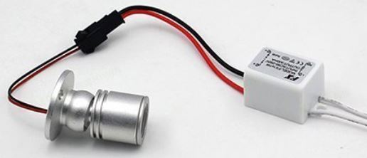
These are 1W LEDs that have a (detachable) AC driver. I hooked them up via an AC power cord and they are certainly bright enough (my primary criteria) and the light is warm in color. These have a substantial housing with a rotational pivot, but that is not a requirement. These have a lens that creates a spotlight but the lens is not a requirement (Edit: I removed the lens and housing, and am happy with how the 'bare' Jorunhe LEDs look).
(One solution that I considered is using a opto isolated relay like this:
https://www.amazon.com/gp/product/B00TGTX23I -- {tho i’ve never hooked up anything like that, it sounds straightforward} with these Jorunhe LED spotlighs connected via EZB, but ideally I would like to have PWM brightness control.
I also considered disconnecting the AC driver from these LEDs and connecting the LEDs directly to the EZB and experimenting to see how bright they can be, but I decided I was likely to either ruin a port on the EZB or burn out the LED. Seeking advice seemed best instead.)
I would be happy to use these Jorunhe LEDs if possible, and/or happy to buy a different solution off the shelf (especially if it is under $40) or as parts. I am semi-capable enough to solder an LED to a cable with some heat shrink, but would prefer (is lazy the word I’m looking for? ha) to pay a little extra not to worry about whether I got the short is minus long is plus' thing correct in all cases, ha
Is anybody willing to help point me in the right direction as to which 'warm light' LEDs (and other parts?) to use and how to connect it to the EZB? Thank a bunch for any advice and ideas.
-Richard Twitch’ R

Can you post a picture of the AC/DC (info side) converter (white box) ?
Hi ptp, yes here you go and thanks
Richard,
Can you confirm the following information (white label): Model: (1-3) x 1W
Input (AC): 85-265V 50/60Hz Output (DC): 2-12V 300 mA +- 3%
You can use a Relay to control On/Off but not with a PWM. Mechanical Relays are slow, generate noise and (cheap versions) will be destroyed with PWM cycles.
You need a Mosfet (Digital Switch transistor). There are a few options you need one that can be driven using a 3.3v logic.
I found this (IRF520): https://www.amazon.com/CJRSLRB-IRF520-MOSFET-Driver-Arduino/dp/B077V57YLN
wiring: Vin - Red (from the AC/DC converter) GND - Black (from the AC/DC converter) V+ - Led Red cable V- - Black Red cable
Logic (3 pin): SIG - White PIn / EZB digital pin VCC - Red Pin / EZB digital pin GNN - Black Pin /EZB digital pin
Basically the Mosfet PCB sits between the led and AC/DC converter output.
Note:
Hi ptp,
But below are 2 corrections Output (DC): 3-12V 300 mA +- 5%
ok i ordered the sixpack of mosfets, and i think i understand the wiring, thank you
(This is probably a dumb question but... ) I would prefer to avoid the AC (and AC driver box) entirely and have a direct connection to the EZB (so that the EZB is providing the power for the LED with maybe a pull down resistor or something?), but i guess that a bright light like this will draw more current than the EZB can provide, is that right?
thank you very much for your help!
@rregister,
You need to keep the AC/DC converter, the circuit converts the correct ratio between Volts / Amps.
Correct you can drive a few mA directly from EZB, not enough for a big led.
To drive a led you need to limit the current, and it's not easy to create a circuit (a transistor and a few resistors) without knowing the led specs.
Since the LED uses DC voltage and draws 300ma the simplest way is to use an H-bridge to drive it. Use PWM to control brightness... Connect one of the H-bridge outputs directly to the LED (you don't need the the ac/dc converter)... Use it as if you are driving a DC motor... PWM will control the brightness...
note LEDs require the correct polarity so be aware of this...
Come to think of it an ESC would work too... Using the servo command in place of PWM... servo command is basically PWM anyway with I believe higher resolution...
@Richard R
Those are the AC/DC output specs. A led per se does not limit the current.
The most important detail when connecting a Led is to limit the current below the Led's max forward current otherwise will damage the led.
You can use a H-bridge to control and separate the load voltage (motor, led, lights) but i still think is important to provide the correct current to the H-Bridge's load.
Some H-bridges e.g. (L298 well know and used here and with arduinos) are inefficient they drop the voltage while driving the load (https://www.rugged-circuits.com/the-motor-driver-myth/) so is another detail.
L298 is an old and affordable chip so it's still ok, keep in mind there are more efficient H-Bridges ICs.
Returning to the Led subject... Maybe there are some exceptions e.g. (Leds with built-in circuits) without more specs and more investigation is difficult to suggest a different power source.
@PTP I have a 12V super bright LED (with current limiting resister) that draws approx 300ma (@12V)... I just tried driving it using a Vex (ESC) speed motor controller.... Worked fine including brightness control... So perhaps adding the appropriate current limiting resister to the OPs led might do the trick...