
Final Step.
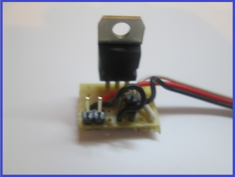
- All done. You should have something like this...
Additional notes You may also use a Mosfet for this switching circuit. A IRL3103PBF mosfet can replace the TIP120/122 Darlington transistor. The circuit is the same however the pins on a Mosfet are named Gate, Drain and Source. The mosfet fits in the same place as the Darlington with the Gate to the left (replacing the Base of the Darlington).
Updates:
Edit 1 (7th March 2013): Underside of board diagram added.
Edit 2 (7th March 2013): For some circuits a diode is needed as shown in the first schematic. The board here does have space for a diode (C4 to D4 - would have to be with legs bent to accommodate 0.1" spacing) however I have not shown one - watch this space.
Edit 3 (7th March 2013): Underside of board optional connections for D1 added.
Edit 4 (7th March 2013): Added diode information.
Edit 5 (18th March 2013): Added IRL3103 Mosfet information.
