I bought this Wall-E about 3 years ago, and I thought it was the coolest thing. I played with it a few times, and shortly after, I began to get bored an thinking how cool it would be to turn it into an actual working bot.
I never really stumbled into anything that would get me hooked (Arduino was one idea when I got introduced to it a year and a half ago, but I was living abroad and my Wall-E was packed away, literally an ocean apart from me).
So a while ago I found EZ-Robot by accident (looking at Make and SparkFun websites for cool components to incorporate into my 2 robots - I also own a RAD v1.0, still sitting tight in the waiting room for his turn to get a makeover surgery) - and the first robot platform I saw being converted was this cute little brother of my long forgotten yellow friend, the Wall-E. Yaay!
So 3 and a half years of waiting, and I am finally at the early stages of turning my old dream into a reality, by making my Wall-E sing and dance (and hopefully do more interesting stuff) under my command.
Last evening I started disassembling him, and in my first post I wanted to only document and share that part of the process with you. With a few remarks that I found interesting throughout. So I hope you enjoy and comment.
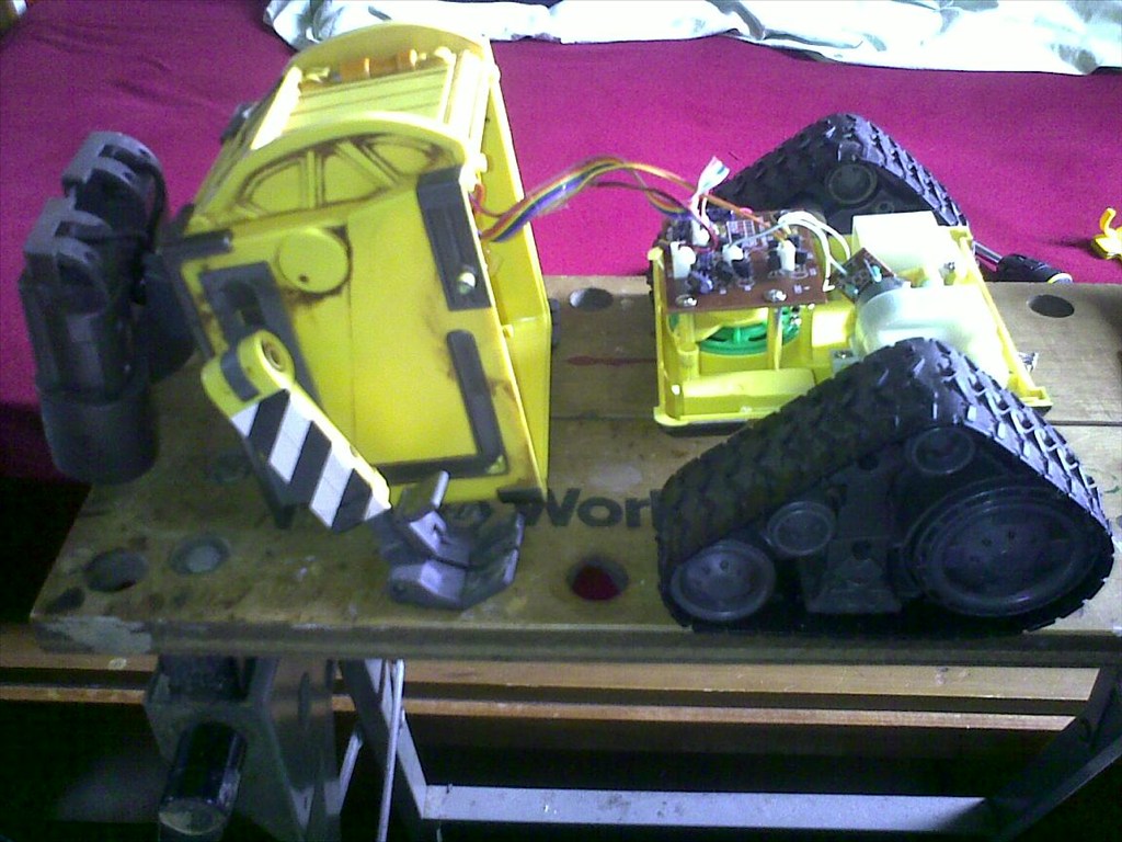
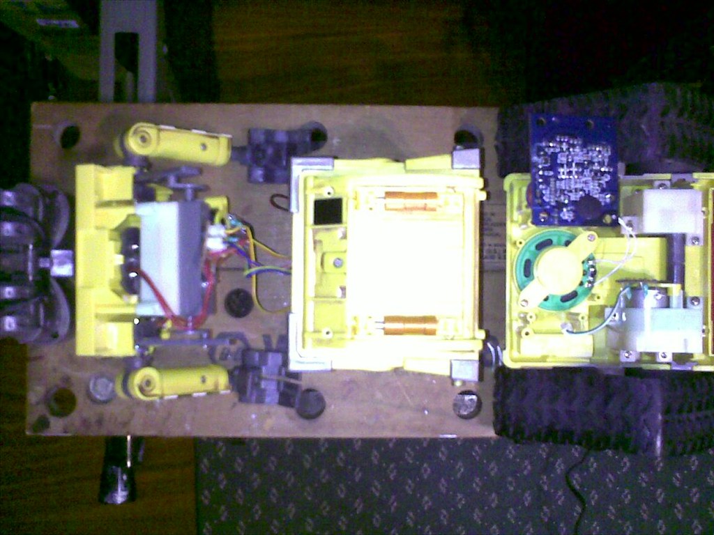
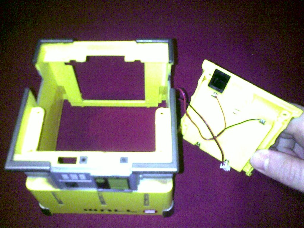
Start of separation of base from main body:
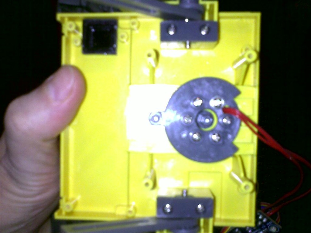
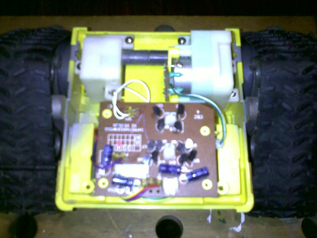
The back of the main PCB showing the "do-it-all custom processing unit" (or, as I call it, the "Big Blob of Black Plastic"):
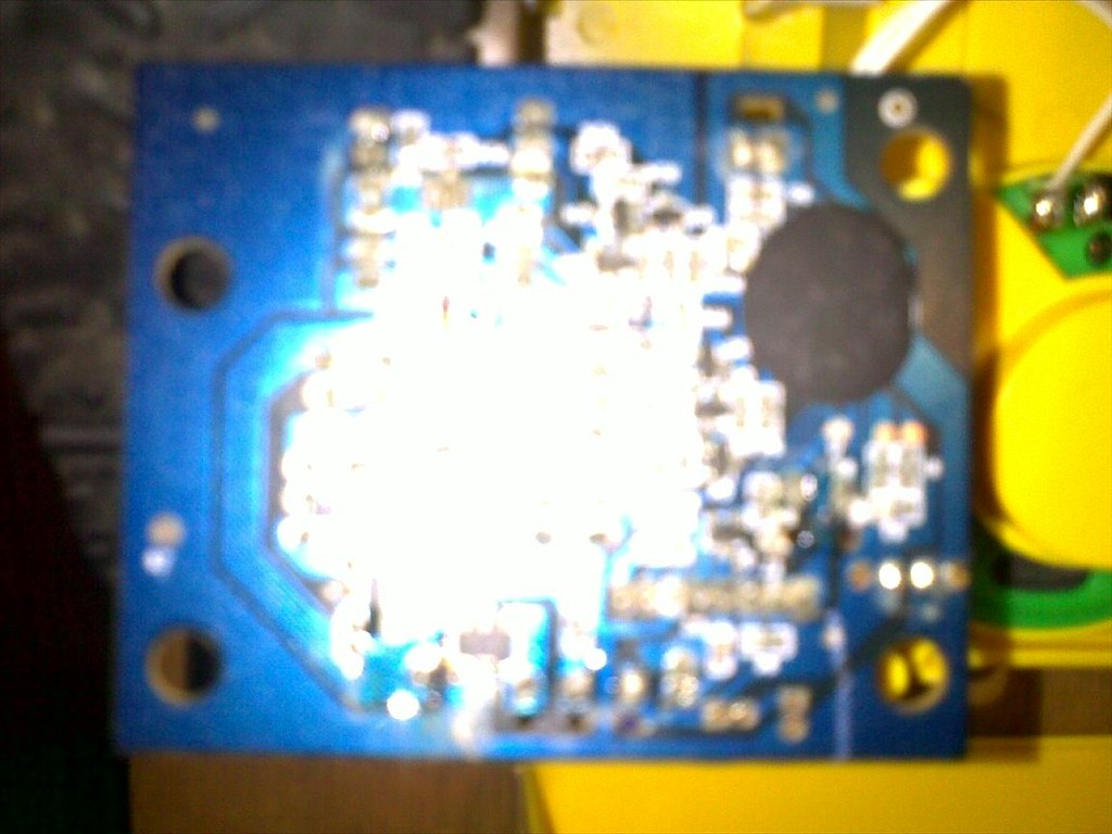
Yep. I was expecting to see something like that - it's virtually impossible to know what the hell is going on under that blob of plastic, unless I get an oscilloscope to look at the signals coming in and going out, and then if I can come up with a truth table for addressing the various sound samples stored in it, then perhaps I could reuse these instead of buying an MP3 trigger board from SparkFun.
(Of course, with a DSO203 handheld scope costing $200 bucks against $49.99 for the MP3 trigger, it's really a matter of dollars and cents against satisfying my scientific curiosity
)
Couple more inside pics:
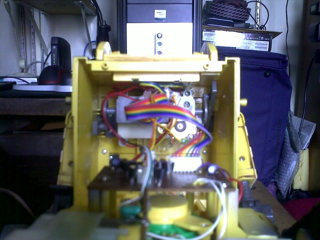
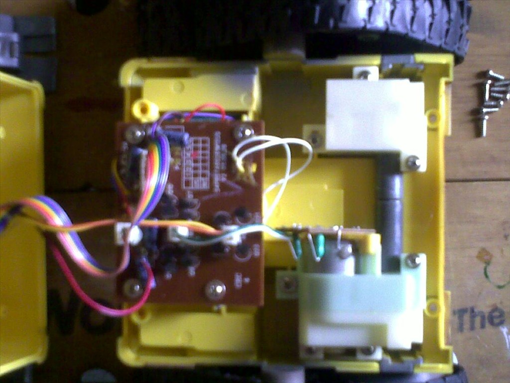
The first thing I noticed is that there are only two motors in this robot - nothing else. All of his movements are coordinated via some very complex crankshaft gearbox mechanisms, activated timely by the big blob of plastic processing unit - one gearbox sits in the base, controlling the wheel movements (forward/reverse/turn/backward), and another is installed in the upper torso and controls the head rotation, eyes up/down and arms up/down movements. I have to tip my hat to the engineer who designed this. A whole lot of movements accomplished with just two ordinary DC motors. Unfortunately, these will have to go (although I am willing to perform some quick experimentation with driving the base gearbox, with the EZ-B board hooked to the existing H-bridge, just to see if I can simulate it going in all directions as I please. If I sense some kind of limitation, then it's definately gonna go.)
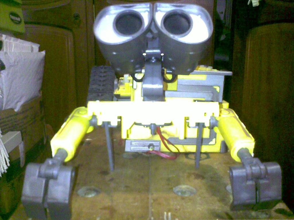
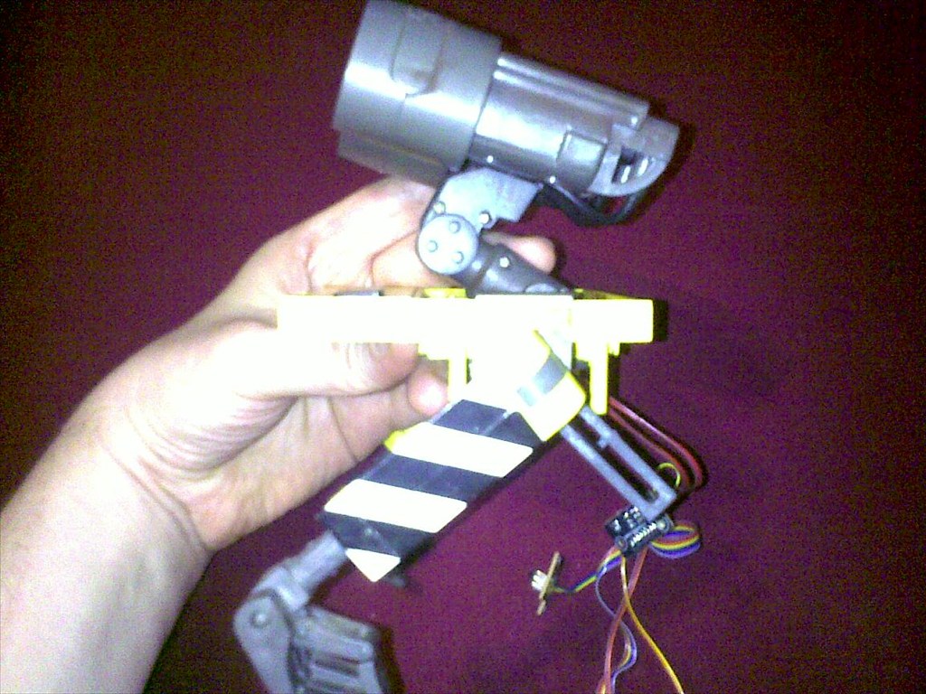
Finally, taken the upper body (head + arms) and torso apart
Front view of the upper body (head + arms)

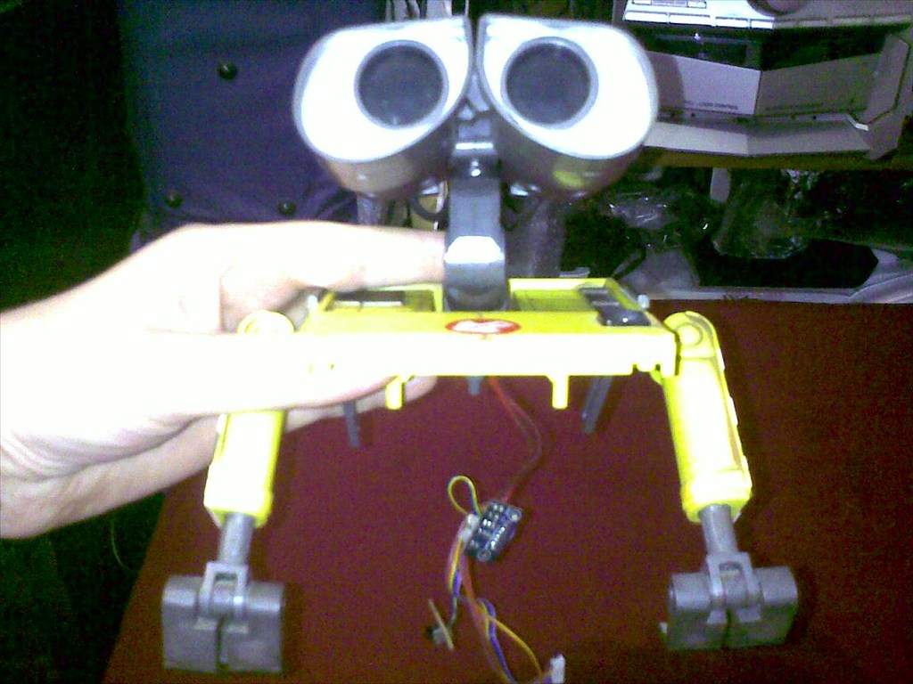
Couple more views from upper body section
Detailed view of the underside of upper body section, showing the hinges for the arms and the head rotating + eyes up/down mechanism (center)
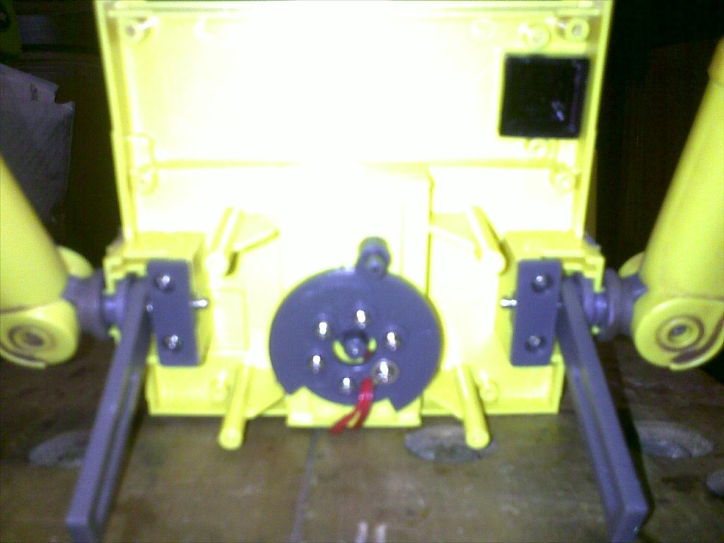
The arms are actuated by these linkages, which in turn are hooked to round actuators connected to the upper torso gearbox. When these actuators rotate, they drive the linkages to move side-to-side, thus driving the arms up/down. I was thinking, maybe instead of cutting the arms and gluing them directly to the
servo head reusing these linkages and gluing the servos to the inside of the upper body section, to make the whole looks more unobtrusive. The same thing could be done to the head rotating and eyes up/down round linkages, it would be farily easy to attach a
servo to it.
Side view, with close-up on the neck
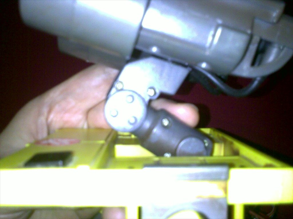
Here's the challenge: The neck is cast into a whole piece of plastic and in order to get the entire head to actually bend up/down, I would need to find a pivot point somewhere that I could attach a horn and link it to another servo, hidden under that section. As of yet, I cannot see a solution that would not involve gutting the neck (I think someone in the forums did something using the camera hinge, I may have a look at that and see if I could confidently replicate it.)


I live in Qatar on a US base. Post goes to the USPS first before it's forwarded here and goes through Qatari customs. The tracking numbers I get from my China orders never seem to be real though. USPS as with any government run agency never improve over time. USPS only got better when FEDEX and UPS offered better service and and cheaper. Here is one example of the mess. Also Google USPS waste. I'm not really saying your wrong but things will get lost when going international. Well....in my own experience anyway.
It still amazes me how a country living under a comunist dictatorship is capable of considerably better postal service than a country that invests billions in warfare and international espionage. But hey, let me stop talking politics or I will soon need sedative. And this is not the place anyway.
I never found a Chinese tracking number to be bogus, hence me putting so much faith in them. But that's just me. Thinking about it, I only had negative experiences buying from the US. What can I say.