

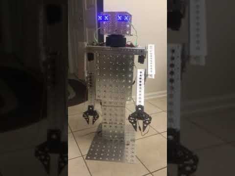
So here I am putting together the first version of the zero rover chassis. My 3d printer was down for a couple months but tomorrow I should receive the new heater to get back to printing so I can make the brackets to mount up the stepper motors.
By jstarne1
— Last update
Discover more robots
Ezang's Mr. Metal Robot 2020
Synthiam ARC controlled Talking Mr. Metal robot with EZ-B4, 2 IO Tinys, RGB eyes, ServoCity gears and DFRobot hex base...

Lumpy's Lumpy's Hasbro R2-D2
Modify Hasbro R2 with EZ-B control, L298 motor driver and 12V LiPo for compact, upgradeable internals, planned dome...
Bhouston's Inmoov Doing Math
InMoov robot performs math using EZ-B v4 and Synthiam ARC scripting, highlighting community-built scripts and advanced...

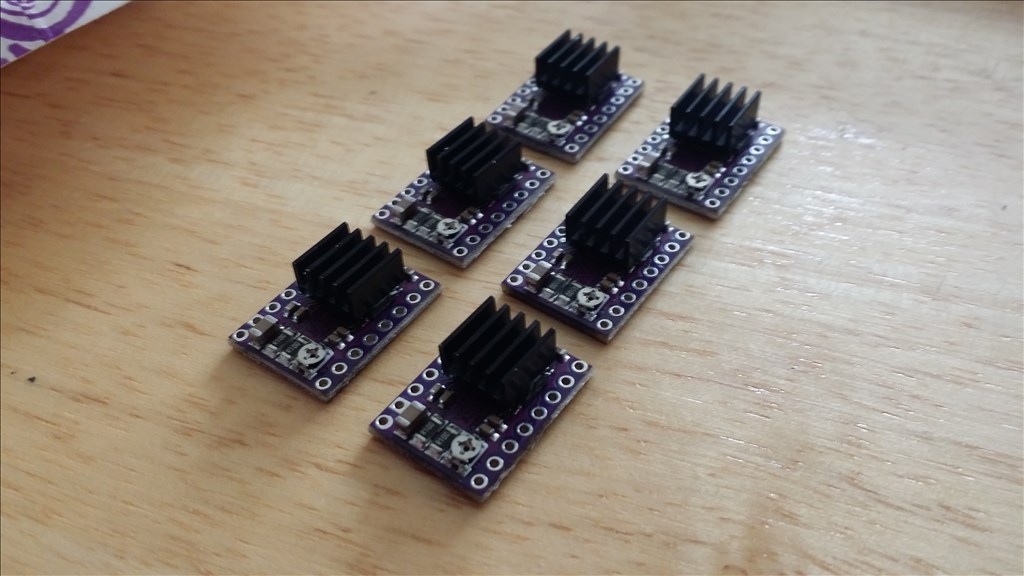
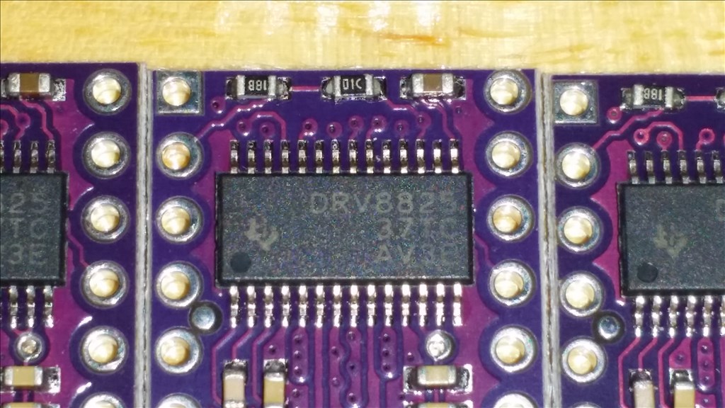
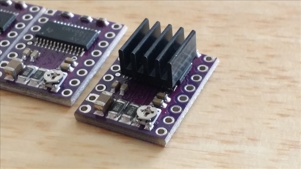
One challenge of going with a drive system that is against the mainstream grain is the controller requirements. First off to answer any questions ahead of time about h bridges.... yes a single h bridge can power a stepper but there are benefits to using a specialized controller. When you apply more voltage than the rated voltage of the stepper is will move faster between steps and raise the torque However the obvious will happen as well. THEY GET HOT. So you can use a h bridge to power a stepper but there is probably not a current limiting feature to protect the motors from drawing too much current. A DRV8825 is a chip made by Texas Instruments and rated for up to 2.5 amps according to their website but one it was packaged with a breakout board the current limitation is 2.2 amps per coil. That's 4.4 amps total. A heatsink is recommended so here I will show the breakout board with 8mm X 8mm glued in place.
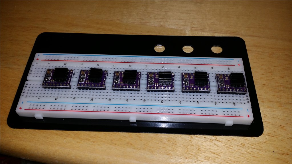
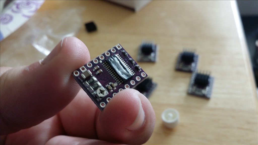
Since I have 6 wheel drive on this chassis then I will need 6 chips to power 12 coils for all the chassis movements. The boards do not come with pins so next I carefully solder up headers while they were held steady in a breadboard.
Cool, What type of glue are you using to attach that Heatsink? Just curious; did you choose a glue by considering it's ability to transfer heat and holding ability under high heat conditions? I imagine that would be very important. I've wanted to do this a number of times so it would be great to know what you used and how you chose it.
Texas Instruments drv8825 stepper driver soldering: https://youtu.be/0yebxwV3tQg
Typically you would solder these pins with the chip facing down and then a heatsink on the other side but I need to have access to the potentiometer that adjusts the current limiting circuit. I will set these later to the current rating of the motor to prevent over heating in the future.
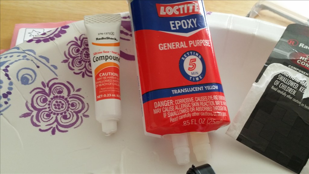
Glue , I specifically used epoxy and thermal compound mixed about 2 parts epoxy to one part thermal. In the future I just recommend using silver powder or aluminum power mixed with the epoxy. It takes very little to attach the heatsink. The old saying " a drop will do ya" is too much lol. You just smear a super thin layer across the top and press the heatsink down to further squish it out.
I chose this just based on availability. It is typically what you use between heatsinks and mosfets or transistors and their heatsinks. There are very pricy compounds that are marginally better and that is useful when your trying to dissipate 100 to 120 watts or more of heat from a cpu but these are much lower heat. These should create under 5 watts of heat , 10 watts if I really turn up the voltage.
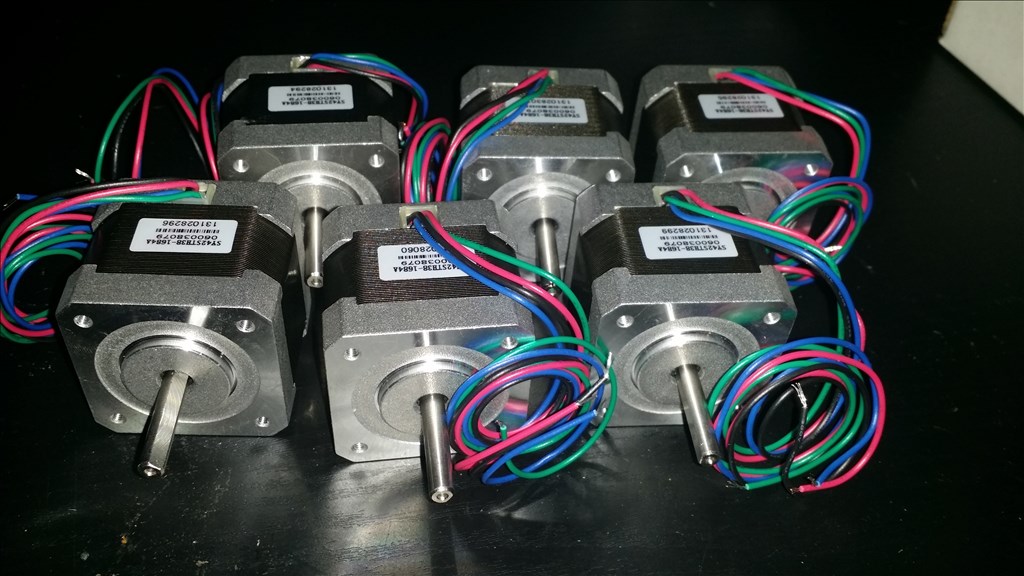
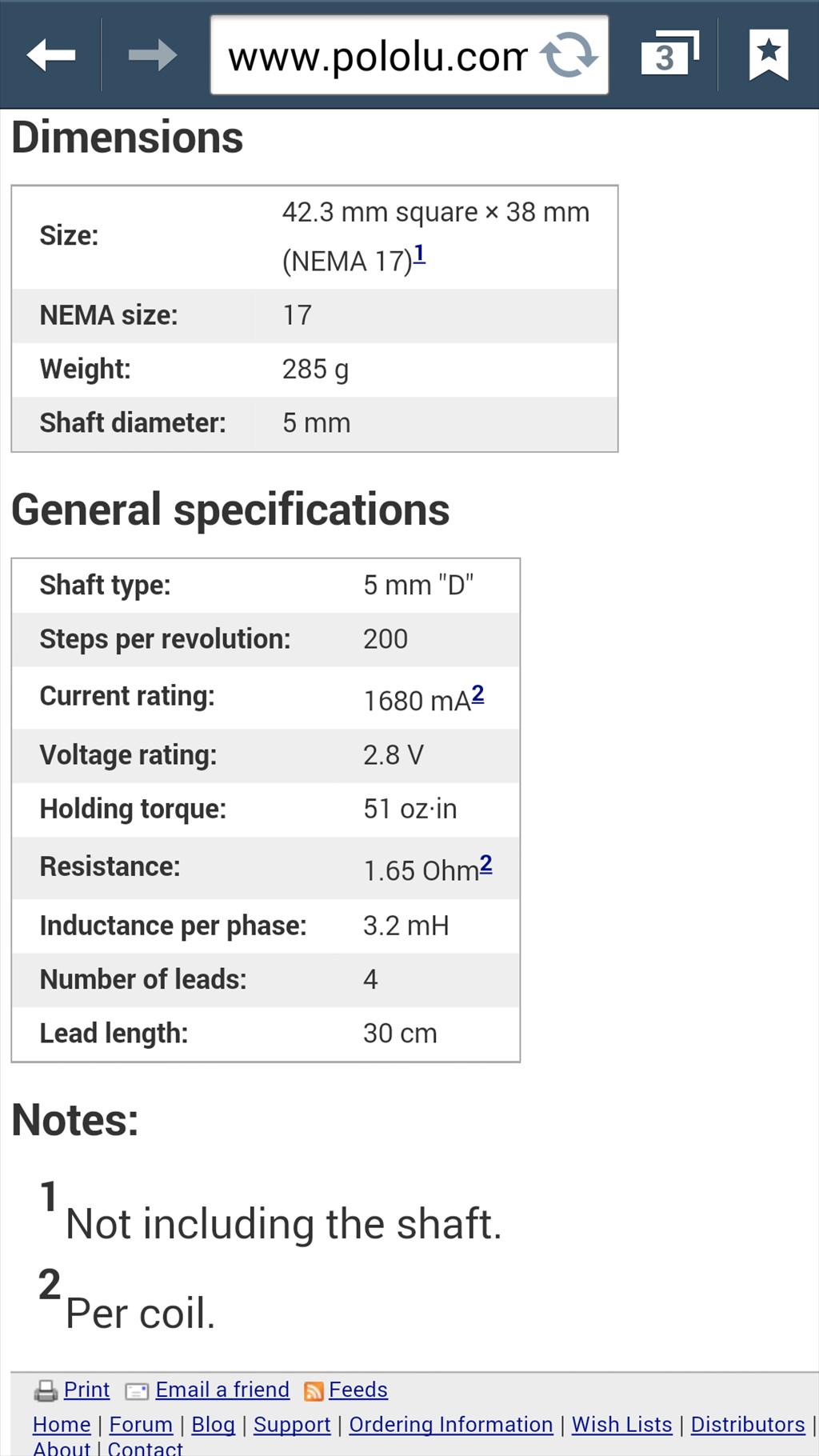
Stepper motors to power the zero rover project
This NEMA 17-size hybrid bipolar stepping motor has a 1.8degrees step angle (200 steps/revolution). Each phase draws 1.7 A at 2.8 V, allowing for a holding torque of 3.7 kg-cm (51 oz-in).
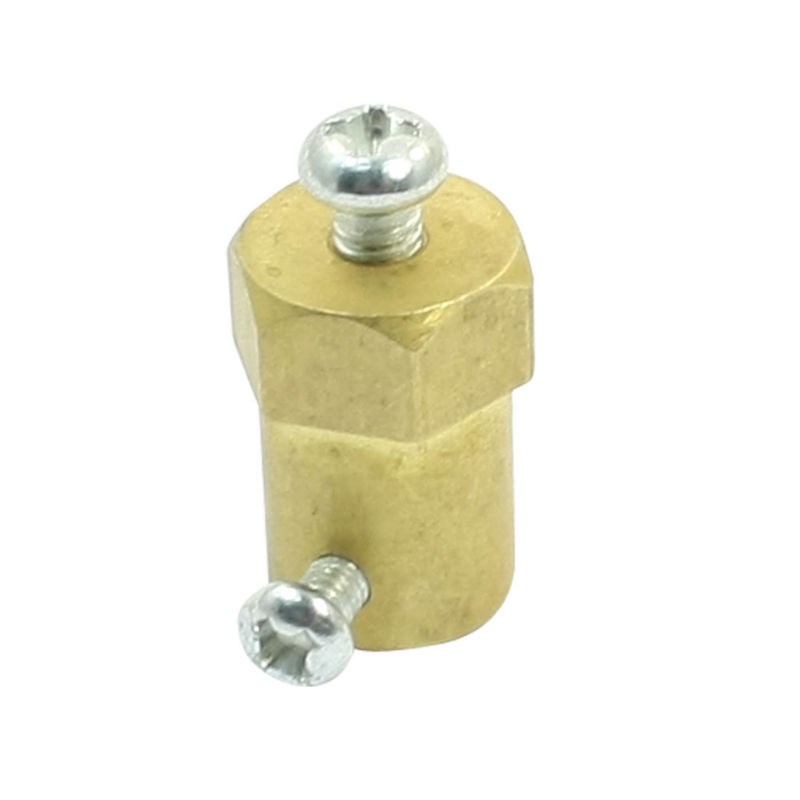
I have 5mm d shaft to 12 mm hex adapters coming that make it easy to connect a rc style wheel to the stepper motors. Designing things this way means modular wheel options and easy changes from on road or off road tires. This adapter keeps the wheel from stripping or slipping around the shaft because it has a set screw to lock it in place. The adapters are brass and commonly used in small robots , rc cars and trucks among other things.
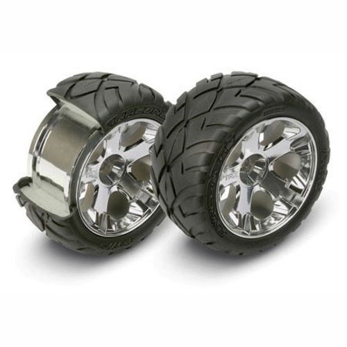
Here is the initial wheel I'm using for scale reasons and I will cost this into 6 duplicates from urethane then spray on a rubber coating. In the future I will print some completely custom wheel options for better fitment and such but this works for now.