


Hello everyone and first of all, scuse me for my bad english.
I am making this robot from about one year, and now, i am beginning to make this "run". This robot, has began to be made from an old Toy.
This was the original toy:

Thanks for EZRobot, i am doing a new robot very better.
I will show the progress here.
By odt
— Last update
Discover more robots
Kullthulu's Artemis - The Household Service Bot
Artemis robot: Max '99 platform with EZBV4, pan/tilt servos, 3Dprinted arms, camera for object tracking/face...
Justinratliff's Data Or Termidata
Centurion security robot inspired by Cylons, Terminator and Person of Interest, built with Synthiam ARC for...
Stevenloffredo90's New To Robotics Looking For Direction
Autonomous box-bot with continuous and HD servos, camera and ultrasonic sensor enabling roaming obstacle avoidance for...

Greetings @odt! What is the info on the original toy? It looks cool already. Why is there a breadboard? Was it some kind of electronics tutorial robot?
Do you have an EZB now or are you waiting for one? I was just curious, could you tell me if you are going to use the V3 or V4?
I can't wait to see what you do with it and the EZB regardless of which version you use.
[edit] I found some info on connecting that robot but no real info about the I-Droid01. The site seems to be broken. https://www.i-d01.deagostini.it/Pc-control/
https://www.i-droid01.com/
So, anything you can share about that robot would be very nice. Thank you. [/edit]
The original toy, was a kind of electronic tutorial robot. But it was not customizable at all and the arms was not motorized, so, it was only an expensive toy... I have found it in a used-things-market.
I have bought a v3 Ezrobot board about one year ago. So i have began to work on this robot.
First thing, was installing 2 biggest motors and soldering a robust steel base on the rear where i will put 3 lead-acid batteries:
Then, i have modifyed the front part of the robot:
And i have placed a mini-itx under the steel base:
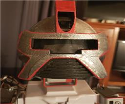
Well, i have beginning to build a different head similar to the Wallee-robot. It is totally hand-made:
Today's progress:
Well, first of all, a picture of new battery-place:
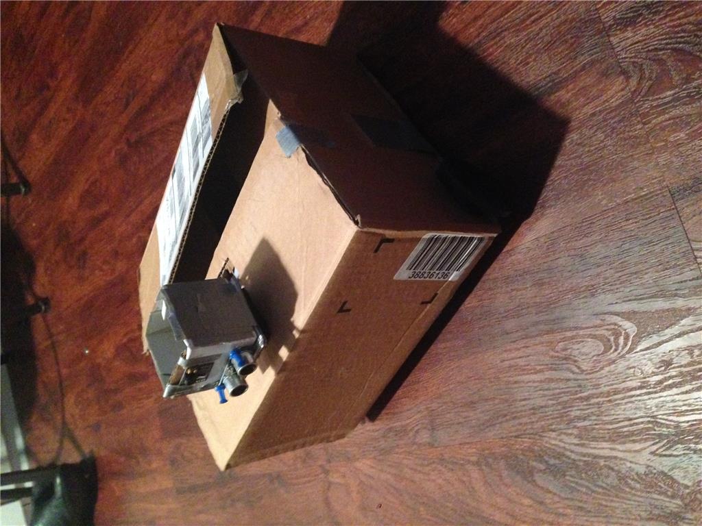
Some boards mounted in place:
This is a relais pack with related ULN298 integrate. The first relay, is used for turning on the mini-pc when power is provided. When power goes down, serial communication goes down too. So, in Visual-basic, a function tells the mini-itx to go 'off' when serial connection has been down for about 10 seconds. The second and third relais, at the moment do nothing.....
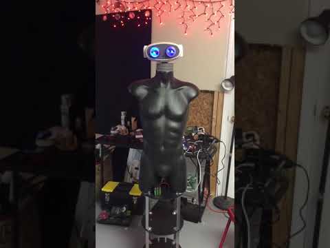
This is how the robot will looks like........
Nice workmanship. Very well thought out.
I like the way your using relays to turn on your Mini PC. I was wondering how I could do this when I end up mounting one in my robot. If I'm reading you correctly your using the operating system on the PC to shut it down when it senses robot system shut down? Is the PC powered from a different circuit but same battery?
i have desame robot.whits i will try to use.
......scuse me for my bad english, but, what is a "workmanship"?.........
things you make whit your hands = is workmanschip like excample a ferrari is made complete by hand.
@ nomad 18.08
You will never have good results with this robot. You will never can make this doing what you want. You only have to use ez-robot to make a nice robot working as you want.
Ok! "workmanship" is a thing made by myself with my hands! Like a Ferrari! Right!
Thank you and scuse me again because i am not well in speaking english.