


Still a work in progress and I have not decided finally on some aspects.
While this is basically the same implementation as used by DJ Sures and others on here, I will post just the few different ideas I have used.
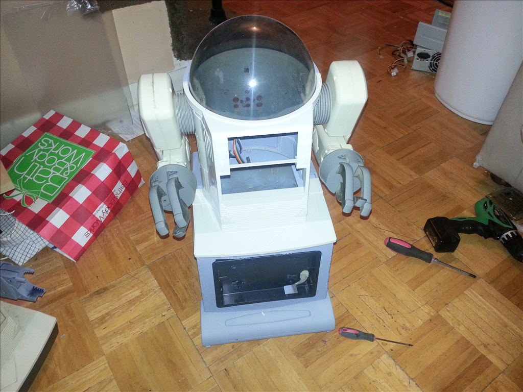
I pulled my Wall-E apart here - Stripping Down the U-Control Wall-E toy
My intention is to largely use the same controls as in the "big wall-e" sample project, with a few more bells and whistles if I can manage them.
Wishlist :
eye-flap action from the original toy
tilting tracks as seen here - Tricked out Wall-E
tilt sensors/accelerometers to try and prevent tipping backwards
personality : respond to ir remote controls as an annoyance (only)
i/r motion detection
and whatever else I tinker with.
I may place this bluetooth hands-free gadget inside hm if there's any room for it. Not sure it will be any good for a microphone, but it should give him a voice, at least.

JOC
Other robots from Synthiam community
Jstarne1's Meet Dusty , Modded Omnibot 4 Home Security Cam,...
Ezang's MEASURING DISTANCE TO OBSTACLE USING THE HC-SR04


To use the great stuff for face and colour tracking from the sample code, at least two servos are needed, one for horizontal left/right movement, one for vertical up/down.
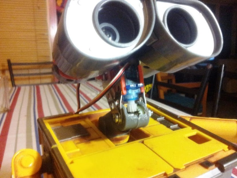
For the left/right motion, I am currently using a standard servo directly driving the neck shaft, using all the original toy's fittings where possible. This places the servo directly under the neck, inside the body.
As I am also using the design shown here (Djandco's Wall.e) for moving the arms, and my horizontal neck servo is placed directly where the green tray holdiing the microservos goes too.
I cut the tray and removed a section wide enough for the servo, then put it all back together. The servo is held only by its connection to the neck plate, and being wedged between the two tray parts. It looks like crap, but it works extremely well, swivelling Wall-E's neck a full 180 degrees.
The servo ends up hanging down right in front of the hole in Wall-E's back and makes it a bit of a pain to get the ez-b and batteries in and out while testing. Perhaps another micro servo would do the job and take up less room.
But I have another idea that I did not yet get working properly, to mount the servo further forward in the body and drive the neck plate via a connecting arm - I may yet go back to that.
For nodding the head up and down, my first thoughts were to put a micro servo in one of the eye compartments - but I also wanted to try that position for the eye-flap (and the other has the camera).
A servo mounted on the side of the neck has been tried elsewhere, and I am as much as possible trying to stick with the orginal toy look and feel so far as I can.
Which offers no explanation as to why I decided to do it the hard way - an elbow joint in Wall-E's neck.
The original toy molds (and probably the original Pixar computer model) have an obvious elbow joint in the neck, but the neck is a solid piece.
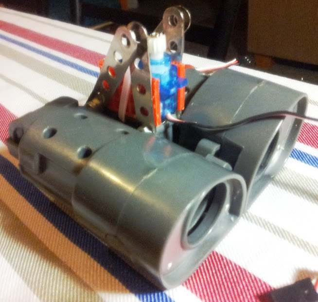
I decided to keep the lower portion of the neck and the clip holding the eye frame bar at the top of his "spine" and replace the upper section of the neck with a frame holding a micro servo. This arrangment hinges at the elbow.
The frame is simply some "meccanno" type construction pieces, forming a triangle with the eye clip section as the base of the triangle. At the opposite corner, a slim bolt is the axle and this is mounted in the elbow.
Wall-E's head can now pitch forward and back at this joint - servo control over the pitch angle comes from re-using some of the neck gear parts salvaged from inside the neck.
A wheel with raised teeth goes inside the elbow joint on one side; a gear wheel is attached to the servo shaft.
Well - it works. (After a lot of fiddling and burning out/jamming at least one micro servo.)
It's probably too much load and the leverage is all wrong, but the action looks quite natural.
Click To Watch Video
At least one drawback in this arrangement is that where the frame is bolted to the eye bar clip at the top, the screw head and nut either side of the clip prevent the eye flap action from working at all.
JOC
Great work so far.........lets see more......
hello, i am very interested in the neck you made....can you post more pics...side angles...and maybe fix the video....
i was able to copy the body titlt in the tricked out wall-e post.....took for freaking ever but i got it...
great pic, got robbed
I've reloaded all my pics here (can't believe I've been only posting thumbnails all this time!)
I'm just using the Google / GMail photo storage, but can't see any way to link videos from there.
So I put the same thing on YouTube so it can be accessed now.
JOC
Very cool neck joint! and thanks for the link to my tilt treads.
Real Life has been getting in the way a bit in the past month, and I have not done much lately with Wall-E. Also been waiting for this latest software/firmware update, and some more new sensors coming in the mail ...
But for those who wanted a few more piccies, here we go -
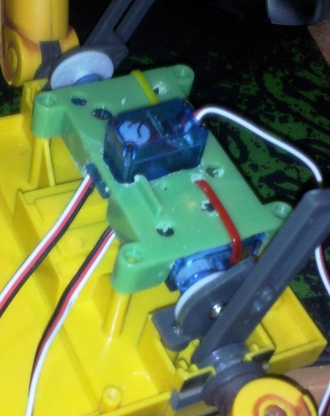
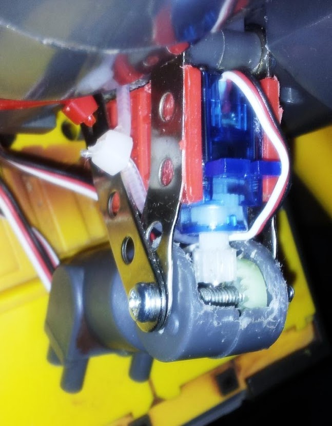
Close up of the neck brace and mini-servo mount.
I applied two pieces of plastic to the servo case to get the right neck width and to help with stability. Even so, you can clearly see a bend in the "mechanno" piece to accommodate the even wider elbow joint section.
Overall, I am not entirely happy with this vertical neck control - there's a little too much play in the joint and the teeth can slip position - tightening the bolt may help with that, but will increase friction.
The tracking software control works ok, but having a definite servo position of say 45 to point the head straight forward will not always give the expected result.
JOC
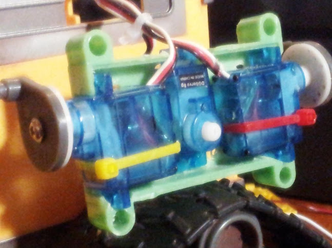
I went ahead and replaced the horizontal control with a mini servo - complete success.
This arrangement lets you re-use a lot of the original neck construction if you align the servo shaft right when it is mounted in that green tray.
JOC
Some general construction tips/ideas/suggestions -
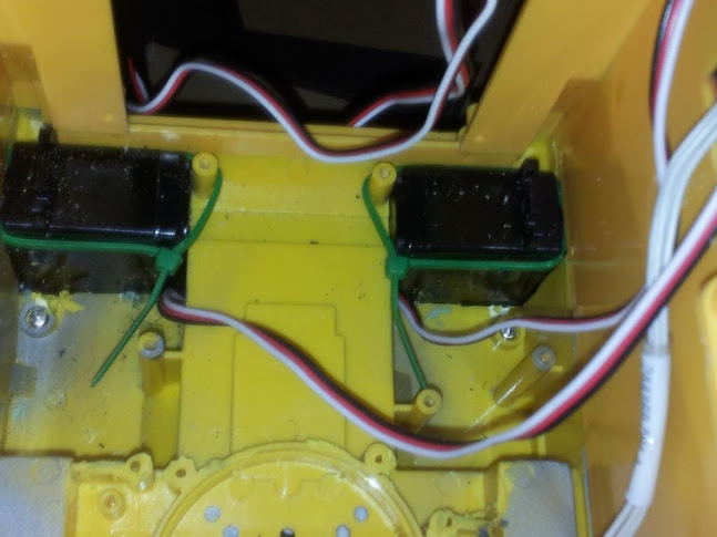
Continuous servos mounted in the case bottom -
I did not cut any of the inner walls that the servos butt up against - the servo shafts protrude a little too far and I used some spacers to keep the track aligned when they are mounted. I would consider trying to keep the outer walls intact and cut the inner if I tried this again.
Still no glue used as yet - there's a little bit of a waggle in these mounts as the bot goes forward, but I have never thought of this as the final configuration - fine for testing though. I have some larger continuous servos I have not tried yet, as well as gearbox/motor kit from an r/c car.
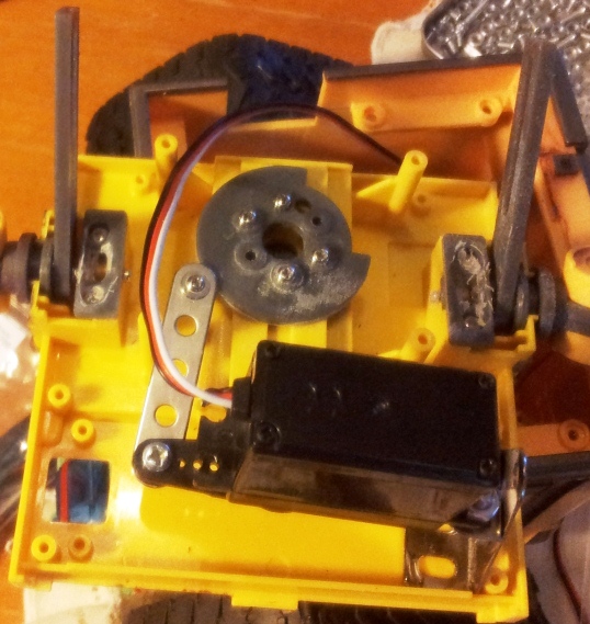
The standard battery pack almost fits perfectly in the original battery compartment without a lid - a little cutting required.
The echo sensor works just fine from down here -
Other detail seen on the continuous servo mounting and the track assembly spacers mentioned above. I also restored the original power switch and wired it in.
Another shot of Wall-E's head -
This is after I remounted the eye camera as cleanly as possible. When mounting the circuit board in the rear section, the lens assembly comes through at about the 7 o'clock position of the front section, looking at his eye from the front.
JOC