jstarne1
USA
Asked
— Edited
https://www.youtube.com/watch?v=UZgQUoEJEdw&feature=youtube_gdata_player
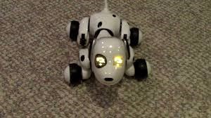
hey I saw this guy in Wal-Mart on posters and immediately thought of the wowwee style toys and ofcourse hacking little dude. Here is a video. I'm sure lots of people will want to get one for their kids and a week later when they get bored it's time for a ezb v4 transplant! the price started as 75 dollars for the holiday season.


I think I found the schematic breakout for CHiP. It calls out many of the circuits featured on this dog to be a coincidence. The diagram has references to the gesture sensors, motor drive, KNRF51822-A24-AAH Karin BT/WiFi module, red/blue LED eye circuit (the dog's mood is interpreted by shades of blue, purple and red in his eyes) and accelerator/gyro. I would also like to note that if this is the schematic break-out for CHiP, then there is a notation of a UART port!
I found this by searching for "Early Light Industrial Co. Ltd" on FCCID.IO website. Below is the link.
https://fccid.io/OKP0820N/Schematics/Circuit-Diagram-2751406.pdf
@TheTechGuru,
Have you looked into using the Pololu IR Beacon for "follow me" ?
www.pololu.com/product/701/
Regards, Frank
I will now!
I already have the watch as joystick thing down, just not the following me without active control : https://synthiam.com/Community/Questions/9125
Alan
I'd love to see this dog with an EZ-B "backpack" wired to its back.
Okay, new update and theory. I think the open solder pads in the dogs head is for a USB TTL module. See my diagram and notes below.
I have one as well watching this thread closely.
I've provided as much detail as I can. Anyone have any thoughts on the proposed USB TTL input? Is there a way I can test it? All feedback welcome!
@bumsteadsean I'm unsure about the port in Chips head, it doesn't really seem like a standard connection, I'm thinking it might be a programming header for the Black blob controller.
I am very hopeful about this mystery port that you pointed out:
This seems like either a UART port or an I2C port. Either of them would likely be useful for hacking. The best way to find out would be to hook up a logic analyzer to the middle two pins and try and decode what's happening while the robot is on. I'm guessing that the 3.28V pin is either the I2C SCL pin or UART TX pin.