GregWW
USA
Asked
— Edited
Good Afternoon Community! I'm making slow but steady progress on rebuilding my Hero-1. I have a question:
Has anyone run in to issues mounting a EZ-B4 vertically?
See the attached photo.
I've looked at all the EZ robots...all are horizontally mounted. From what I can see, the power connector and the magnets are the only "things" holding the processor in the base. I'll have to come up with a way to secure the processor in the base so it doesn't vibrate out.
-Greg
Ok...Let's try this again https://www.ez-robot.com/emicons/emo_smile.gif
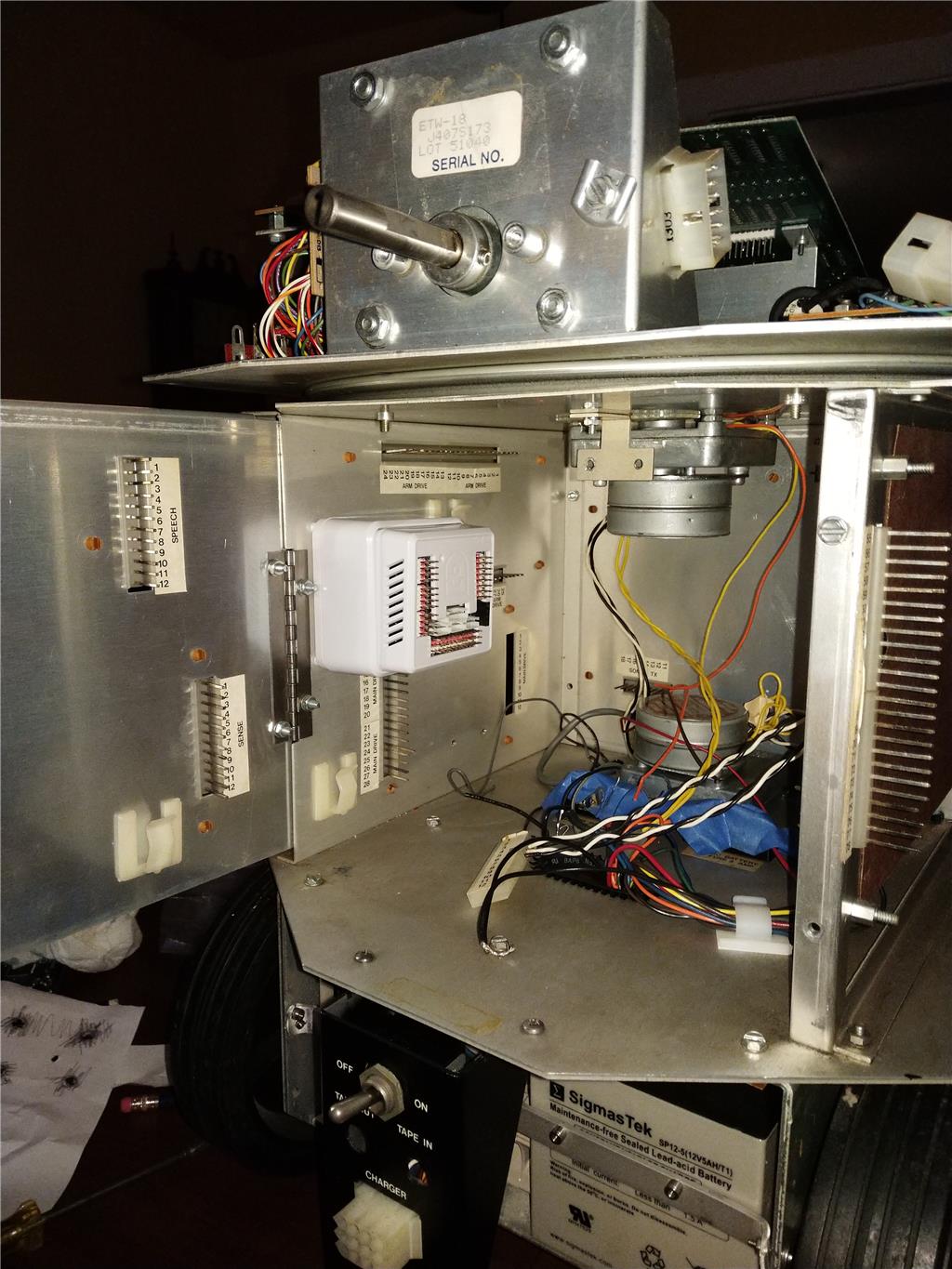
Hi Greg!
It seems that somehow the picture didn't get attached.
I've mounted an EZ-B vertically in my 18" R2D2 I just used some good ol' hot glue with the Power base.
Thanks Jermie Photo now up loaded.... So you didn't hold processor module in the Power base. It never "wiggled" out while the robot was moving? -Greg
That's a nice photo! Pretty awesome that you are converting the Hero-1 to use an EZ-B!
I've never had it wiggle out but if you're a bit fearful of it happening you could always place a bit of hot glue around the legs of the EZ-B enclosure and quickly mount it back in the power base. If you ever make a mistake, spray a little isopropyl alcohol on the affected area and the hot glue will easily release. It's a little trick someone taught me some years ago.
Thanks Jermie That's a neat trick! In my head, I had some kind of "rubber band gizmo" that would hold the module in the base. I was wondering if anyone had come up with a wiz-bang way of holding in the base.
Thanks Greg
Come to think of it, I've not sure how old your ez-b/power base are but if they are fairly new the installed magnets should be sufficient to hold the ez-b in place. The magnets are there for that very case. The ez-b is mounted vertically in JD.
If it is older and doesn't have the magnets, you can also just run a strip of tape around the edge of the base and the EZ-B to hold it in.
Alan
Alan: I tried your idea last night.... It totally worked! I used 4 pieces of electrical tape around the lower edge of the power base. See the attached pic.
I did a shake test afterwards... the processor module is stoutly held by the power base. I took a video the of the shake test, but I haven't figured out how to upload an MP3 file yet....("add YouTube Video" only loads a URL ?)
Thank you Alan -Greg
You'd probably want to create a YouTube account if you don't have one yet and upload your video there, then you'll have a link to your video and you can share it.
Ok Got it Thanks! Greg
I duct tape mine around the base to keep secure in InMoov and other rough duty project. I also use heavy duty Velcro to keep entire unit intact especially when using Sabretooth, loss of unit the robot keeps on going.
@jackphillips1953 - what I am hearing is you need a "signal loss self smarter" so as to make the robot no crash - no go boom!
What is "signal loss self smarter" or just a joke?
As all have said, no real problems with mounting the EZR controller vertically. THe magnets seem to keep mine secure enough in use. Tape is a simple solution as outlined above.
I did design a simple adapter that allowed me to mount it while still allowing access to the fuse if it blows.
https://www.thingiverse.com/thing:2501214
>"signal loss self smarter"
Yes I was half joking and half revisiting an idea others have tossed around before.
Like you said, if you lose your ezb your robot keeps going and on a large robot that's not great because you're going to damage your robot or your house or your self, etc.
Secure mounting methods are the easiest way and probably cover most scenarios.
Some heavy duty robots or robot builders might want a some sort of signal lose or "heart beat" monitor. I wonder if there is such a thing in the R/C world?
Justin,
I know about runaway robot. Not fun. I guess no solution to this.
My 2 cents on the "signal loss" issue... There's a concept in high reliability control electronics called "Fail Safe" design. The idea is, that if the main processor goes south, or fails... control lines are pulled to a safe state by discrete components. For example.. a trigger wire from the a processor turns on a motor...active high trigger. A pull-down resistor.. maybe 5k to gnd would be used..so the line is pulled low if the processor loses power... stopping the motor. Another example is if an E-stop gets pulled.....the machine isnt allowed to just start up again, unless a safe power up sequnce happens. There's a whole science to it referred to as SIL levels...(SiL)...Nuke power plants have highest level, SIL 4 -Greg
Ok Figured out how up load video of "Shake Test"
@Justin, Just a quick thought, use the power from one of the servo power pins to power a relay. The relay when engaged passes power to the rest of the robot. If the EZB comes off the base the relay disengages and no power to the bot.
Yep... that's one way of handling it. -Greg
My electronics knowledge is limited, but I think when this has been discussed before the conclusion was that you also need a pull down resister to the relay. That way if the EZ-B loses communication but still has power, and the pins float, the signal will be pulled low and release the relay.
Someone please correct me if I have this mixed up.
Alan
Anybody do this?
Is there a bit from the EZB that will toggle in a "loss of comms" event? That way external hardware could trigger an alarm and do a graceful shutdown -Greg
I have been searching (unsuccessfully because I can't seem to properly narrow down the search terms) for previous discussions about this. I did find a post from DJ that says all ports will go low when the EZ-B loses connection, but I have definitely seen other discussions where ports floated and might not be seen as low by a connected device. Not sure what the actual current status is since most of those conversations predate the V4/2.
Perhaps some experimentation is called for... Empirical data always beats documentation anyway.
Alan
I agree with you Alan. If it's true that all ports go low or float with a comm loss...then you could set a bit with a pull-down on it, high while running. Monitor the bit externally and trigger an alarm when low...is it that easy or am I missing something? Greg
I'm thinking the difference is "lose of power" in the ezb vs "lose of comms" in the discussion. It would stand to reason that the that EZB might do as you recall from an old thread (I recall it too) that the ports go low if the EZB loses comms and I would view that as loss of wi-fi, but the robot and EZB is still powered. So the robot should just relax and stop in a revolution robot (a comm going LOW could be something else in a custom robot).
But if you lost power or the EZB fell out of the robot I would tend to think there is nothing to pull the comms low and they would float.
That is what I think - not tested. Now I want to test it.
@Justin, wouldn't loss of power, by defenition be low (0 volts)? I think that is the easy one, but comm loss is the tricky one.
@GregWW, yes, I think it is that simple. If you connect to a relay, don't even need a different logic device to monitor. Pin goes low, relay disconnects power to the drive wheels.
Alan
Hi Greg,
I mount the controllers vertically all the time in my large scale robots. I remove the top cover of the power shell and carefully mark and drill 1/8" holes though the plastic shell at the location of the 4 board mounting holes. Four 4-40 x 2.5" screws and locknuts secure the power shell to a vertical panel. Here's an example from my latest ARMadeus Mk. 12 robot.
Or if you're worried about the EZB coming loose from the powershell........... you could just trash the power shell, cut a hole EZB's plastic shell for wires to pass through (or get rid if this shell also), unsolder the Deans power pin and solder a pigtail to the EZB's power input points where the Deans pin used to be. Install a Molex connector on the pigtail for easy disconnection. Don't forget to install an inline 20 amp fuse on the positive leg. Problem solved and you have less bulk and a better power connection. I have 4 EZB's in my robot and have tossed all the power shells. In my opinion the power shell is Just another unnecessary component in a DIY robot that adds an unreliable power connection and complexity.
Wow, thanks guys for the great ideas. So Dave, you got rid of the funky Deans connector all together. I thought of that, but this is my first Bot and I wanted to see how well the base performed. -Greg
My problem is with Sabretooth. When I send a command it keeps going until I send a stop command. So if I loose communication it keeps on going. I am not sure that there is a way to stop it.
With the relay idea, you could just cut power to the Sabertooth, or even the drive wheels.
Alan
Which model sabertooth are you using and are you using it in r/c or serial command mode? On most models when in r/c mode there is a dip switch setting to enable a Timeout Failsafe, which will shut down the motors if the Sabertooth stops receiving correct signals from the receiver. If using Packetized Serial mode, you can send a command to enable the timeout failsafe.
Hi Dan,
I will look but I believe serial from EZ. Also having a hard time with speed control. Nothing seems to work. It is InMoov so I want him to creep slowly around.
another quick thought. Write an EZ-Script that sets an analog pin high then back low at a given rate. Using a 555 timer setup as a monostable multivibrator use the output to drive the relay. As long as the script continues to refresh the analog ping the relay stays engaged. If you lose communication the refresh does not happen and the relay disengages.
And if you lose power, again the refresh would not happen and you again disengage the relay
After reading thru the rest on the posts, if the EZB does go high impedance when comm is lost, then you can drive the relay form a analog pin with a pull down resister.
No.
I did a simple test: LED connected to a digital port. Mobile Application toggles the EZB digital Port. If you switch off the mobile wifi, EZB keeps the port state On or Off.
Thanks ptp, so the EZ solution is out.
Sabertooth:
The 2x25V2 (2012) https://www.dimensionengineering.com/datasheets/Sabertooth2x25v2.pdf
Has the Timeout Failsafe for RC and MicroController Mode
The 2x25V2 (2007) https://www.dimensionengineering.com/datasheets/Sabertooth2x25.pdf
Does not have the Timeout Failsafe, but supports an Emergency Stop switch (Active-Low). If you pull the S2 Input to Low the Sabertooth shutdowns.
Basically is an Emergency Stop Button but can be driven by a circuit logic to stop when a communication is lost.
I don't have time to test this out today, but has anyone tried:
in their EZ-Script?
If the test fails, you still can not communicate with the EZB to tell it to halt the motors.
Software can solve a lot of problems. I had develop a similar feature (firmware) for the EZB 4 (v1).
EZR released a new EZB4 1/2 Top, so its possible to extend the software (firmware) to implement that feature, ask a timeout without receiving any instruction from the ARC, and the target Hardware Port and value (On/Off) that way you can control a relay or interface with another device e.g. Sabertooth Emergency Stop Switch.
You can try email your wish list to the Santa Claus (6120 11 St SE #10, Calgary, AB T2H 2L7, Canada) maybe can be implemented in a new firmware release.
Tip: Add some rubber ducks as gift, i heard the Santa collects rubber ducks.
@ptp, That is a fantastic solution. I would not be surprised to see that in the next release.
Basically what we need is a timeout switch, resets the state every time a condition is met e.g. (port value change On-off-on-off... / or no communication from ARC/TX line is idle:high).
you can do it with:
555 timer - @rz90208 solution
555 timer - Monostable Mode: https://www.instructables.com/id/555-Timer-Basics/ https://www.electronics-tutorials.ws/waveforms/555_timer.html
I remember to play with the timer long time ago.
Or some capacitors, resistors and mosfet.
use a micro-controller to sniff (monitor the serial TX) from EZB4 Top part to the bottom part, define a timeout when no bytes are transmitted to the EZB bottom and then control a relay or another circuit.
Hi,
maybe a timer will work. isconnected() is no good because a stop command needs to be sent so because no way to communicate unless you try a reconnect and a stop. But if out of range your done.
Here is a 555 circuit that should work. R1 = 10 ohm C1 = 100 micro farad This will make the duration of the output pulse 1.0999 seconds So as long as you pulse the input every second the relay will stay engaged. Don't forget you will need a driver on the output of the 555. Thank you Forest Mimms, I have and love his books.
@rz90208: Nice!
Which book ?Can you adjust the R/C values for +- 2 seconds.
@ptp tp = 1.1R1C1
Timer, op amp and optoelectronic circuits and projects.
Leaving the cap at 100 uf and using a 100 ohm pot you will have from .11 at 1 ohm to 11 seconds at 100 ohm
I look forward to seeing what your going to do with this guy!
Here you guys go: https://synthiam.com/Community/Questions/11633