
Rural Geek
Canada
Asked
— Edited
Using Acd For Switch Inputs
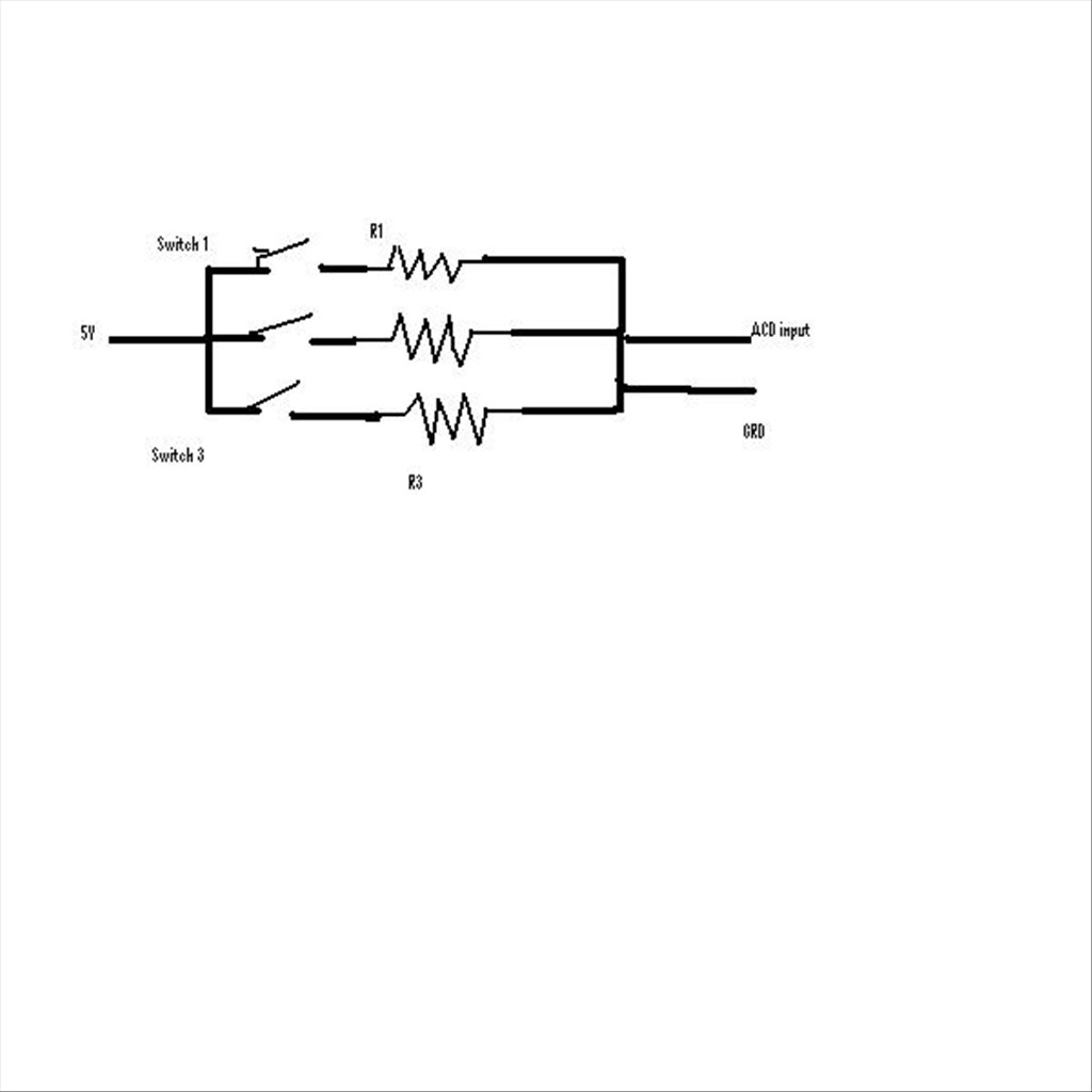
I am putting bumper switches on the back of my bot. I am trying to save on Digital ports so my idea was to use resistors and acd input. Here is a very crude drawing for the idea I am talking about. What I am wondering is if it will work as I think?
When a switch is closed the acd will read the resistor and I can use the software to figure out which switch is closed.
What do you think. I just want to make sure i don't let the factory smoke out the the EZ-B.

I think it needs more than just 1 resistor for it to detect which switch is closed. Resistors would reduce the current but not the voltage... Please, someone correct me if that is wrong.
I'm thinking you would need to reduce the voltage, so some kind of voltage divider/reducer circuits after each switch.
Actually, I think I am wrong... I need to learn to stop coming on here when I should be asleep...
That's how I would do it...
I haven't worked out if SW1 & SW2 closed, SW1 & SW3, SW2 & SW3 and SW1, SW2 & SW3. You may need to use different values if some I haven't worked out work out to the same. It's too late for me to think about the harder ones...
The signal needs to be grounded with a resistor, otherwise the pin will float and read crazy voltages
Thanks guys for the help. I'll try it out and let you know how I make out..
@DJ would it matter what size of resistor I used on the signal to ground I was thinking of around 3K.
Try at least a 10lk first.
ok thanks dave