

Using 123.Circuits.Io Schematics Pcbs & Breadboards
Circuits.io is an online, browser based schematic drawings, PCB design and breadboard simulation package by AutoDesk. It can be very useful for testing out circuits before you even get around to physically building them and even has a built in Arduino script simulator (which can be useful for testing out how switching of ports or ADC values can effect circuits).
The software is pretty simple to use however I decided to write some tutorials on how to use each of the different parts of this software and have a step by step guide on building circuits.
Below are (or will be when I finish them all) tutorials for each part. This will be updated to eventually cover all parts however, for the time being I only have the schematic section completed (bear with me on the other two).
Circuits.io Schematic Tutorial
The first thing you need to do is make sure you have an account, so point your web browser to https://123d.circuits.io/circuits
Then click on either Sign Up or Sign In depending if you have an account or not.
If you don't have an account simply sign up for one. You can sign in using Facebook too to save you filling in any forms.
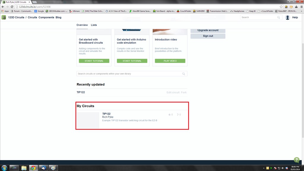
Once you have signed in you should be greeted with the main screen where you can see their tutorials, your previous projects or create a new one. We will want to create a new schematic so go ahead and click on the New Schematic button.

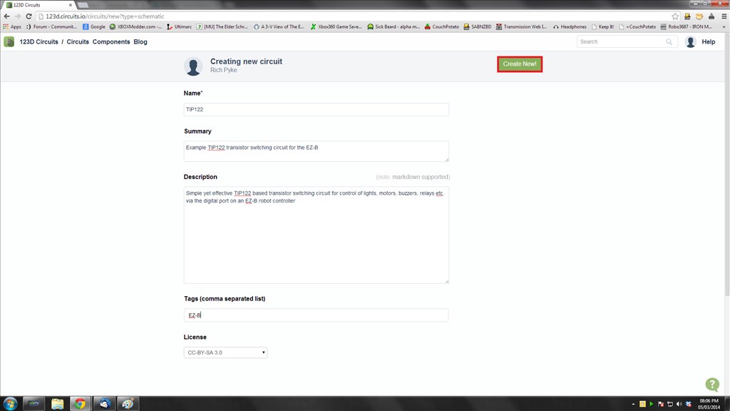
Now you need to fill in some details about the project such as the title, a summary, a description, some tags and finally the type of licence you grant.
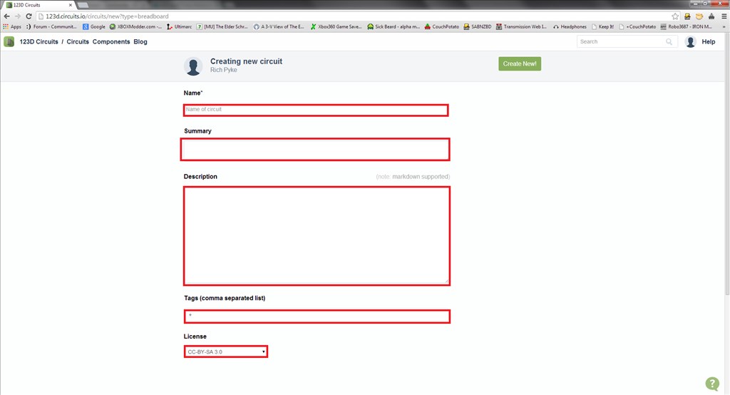
Go ahead and fill it all in.
You should now be greeted with a nice blank canvas to play with and a pallet of tools and symbols to the right of the screen.
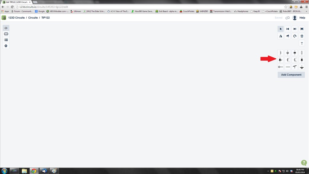
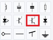
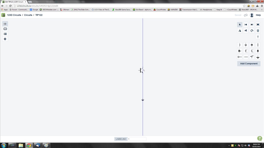
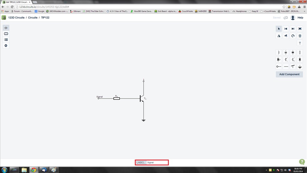
So, let's make a simple schematic for the trusty old TIP122 transistor switching circuit. The first thing we need is an NPN transistor so we click on the symbol for an NPN transistor
And we place it down on the canvas with a left click

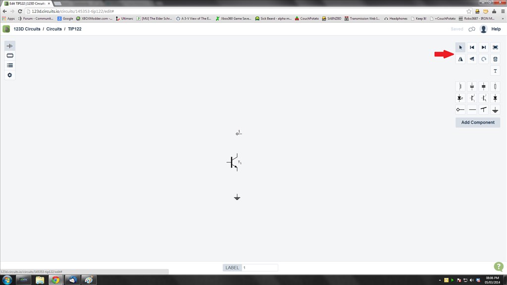
Next we want our ground so we select the ground and place it on the canvas too, notice at this point we get a blue line to aid in aligning with the other parts already on the schematic.
Next we add a node, which will be going to the item the transistor is switching, be it an LED, lamp, buzzer, motor or whatever, so select the node and place it down. The node will be at the wrong rotation so once it's placed down click on it to highlight it and select the rotate button from the pallet of tools.
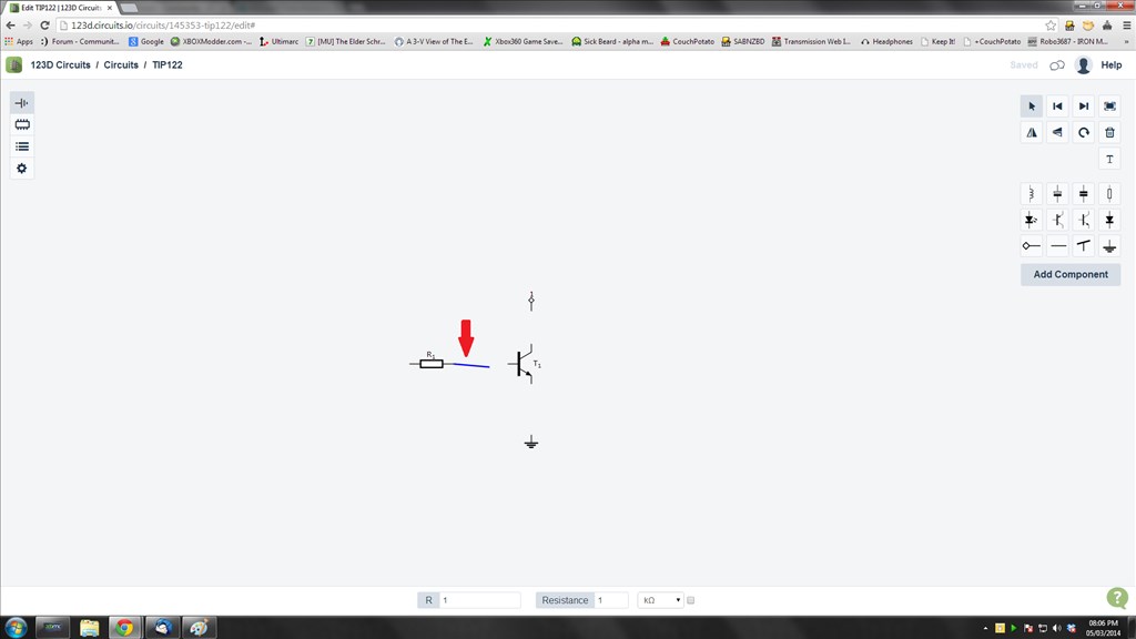
Next we need to add a resistor, so select the resistor and place it down
And now it's time to join it all up with circuit lines. To add these simply click on the end points of any of the components, a blue line will now be joined to the component and your pointer, then click where it needs to go to and the circuit line is added.
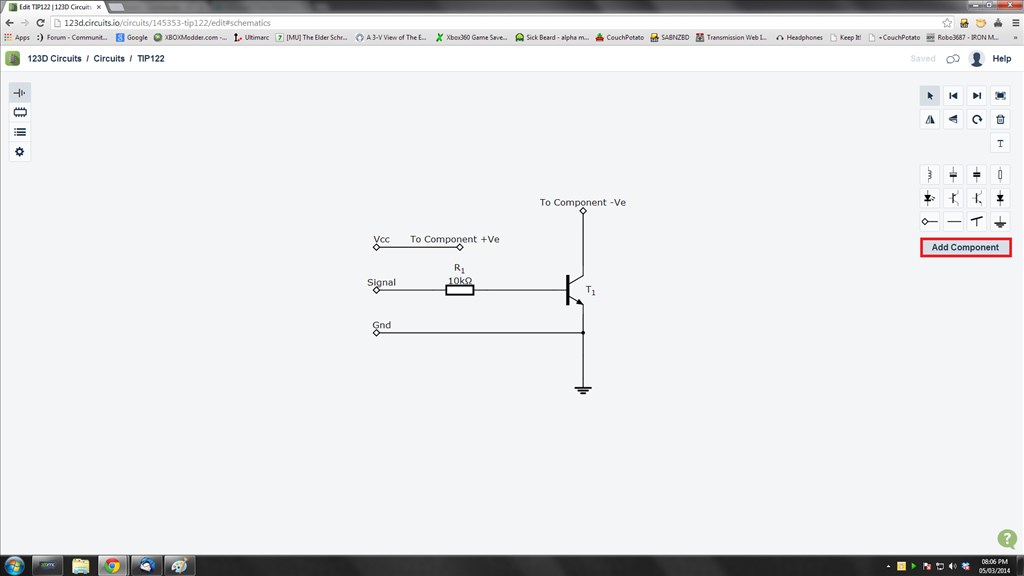
Add in the other components, nodes and circuit lines to complete the circuit. Then add in the labels for the nodes. To add the labels, or to change the values and part numbers of the components click on them, at the bottom of the screen the information will pop up, simply click in the box and adjust the text to suit.
And we have our circuit.
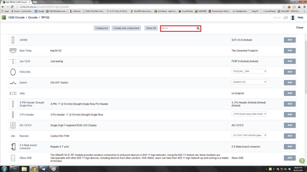
If the component symbol you need isn't in the pallet, for instance a relay, the option to add a component is also there, just click on it
Up pops a dialogue with a whole range of new components. Use the search box to narrow down the search. Click on Add to add it to the pallet.
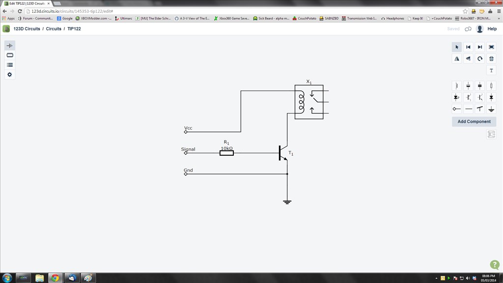
Then add it to the circuit like we did with the other components, click on the icon in the pallet and place it on the canvas. Connect it up with circuit lines and viola.
The circuit will automatically save throughout drawing it so next time you go to the main screen the circuit will be under your circuits.
And that's it, you have just drawn a circuit schematic. You can print this, share this or edit this all from the main menu. Just click on the circuit picture or title and it will load up all of the information you need.
PCB Tutorial Coming soon
Breadboard Tutorial Coming soon

:D Cool Beans Rich! Nice Tutorial
Thanks. I missed a few steps when grabbing the screens so I'll probably add more in to the schematic one once I've posted up the breadboard (next) and PCB ones.
Rich , this is great! Thanks so much for putting in the time from your busy life to make a smaller learning curve and this easier for the rest of us to understand. This is just in time to help me out in my project. We're very fortunate to have you as a member of our family here!
@Rich and all others interested,
I have to say I really got frustrated with 123D Circuits. At first glance it a nice program that seems easy to use. However I quickly found that if the symbol I needed wasn't in the pallet of the schematic editor it was near impossible to get it into my schematic drawing. The available and (very limited) symbols that are there in the pallet work nicely though. When I went to add symbols I found other users that were able to use different symbols in their drawings and there were also symbols available that others created to share but I found no way to use them in the my editor. I spent precious hours trying and also found no help on how to do this. Now, I was able to add components that showed up in the Breadboard editor but they would not show the schematic editor.
I gave up and started looking elsewhere for a schematic drawing tool and quickly found a lot of choices. I settled on Scheme-it, It's a free drawing tool offered by Digi-Key and very easy to use. It operates almost exactly like 123D circuits but has a ton of available symbols a loads more features. Just a couple examples; right out of the editor I can look up the component I want, get all the specs and then paste a picture of it right into the drawing. The learning curve is very low and with a little playing around I was able it change, resize and move things around nicely. When it comes to saving the project I can save in in several formats or ever share it anywhere. I highly recommend this program over 123D circuits. Only small drawback is that you need to create a free account with Digi-Key. No need to giver personal info. Here's a linky:
Scheme-It
Here's a nice little circuit I just drew up. It's a high side switching circuit that can be controlled by EZB to switch on and off a Sabertooth or other controller:
Hope this helps. Have fun!
Thanks for the feedback, I'll have a look and see if I can cover adding custom symbols (I know it's possible as I have done it but I'll record the steps next time).
I'll give scheme-it a shot too, it looks pretty good. I like it's showing what Q1 and Q2 are too
Another alternative (which I plan to cover, eventually) is Express PCB however it lacks the cloud based/browser based features but it's full of symbols, easy to make and add new ones etc.
Unfortunately, at the moment I have very little time on my hands with work being insanely busy and private life taking up most of my weekends for the next couple of months, even my week off over Easter is full of appointments so I have no idea when I'll get around to anything at the moment. I may just give up trying to find time and scan in my notepad
Cool , I will check it out.
I totally understand not having time. Today is the first day in months I was really able to sit down. tired
If you can figure out how to add a custom symbol not listed in the schematic editor I'll take my hat off to you. I tried for days but your more savvy then me on these things. I just felt 123d circuits need more polishing in areas like natively available symbols, saving & sharing a project and community & customer support help.
in Scheme-it the labels you mention are easy to edit in the details of the components you add by double clicking on them. Then you can either choose to show or hide different lines of the details. I chose to hide all details except the Name label and then added the rest on the pics I inserted on the right. You can easily also add, size and position text. That's how I added the leg letters for the Transistor and Mosfet.
Dave, I also believe that the Scheme-It should be good than the 123D circuits as it is provided by the digikey and I feel as electronic parts distributor they should have more resources than 123D circuits but It definitely try it.