Asked
Resolved Resolved by DJ Sures!

USB Connection To EZB V4

OK guys I have another question for everyone can you use the UART on the EZB V4 to connect to a USB rather than the camera port?

I want to hardwire my EZB's to my onboard PC but I also want to use my ez-robot camera with one of my EZB V4.


Related Hardware EZ-B v4

ARC Pro

Upgrade to ARC Pro

Join the ARC Pro community and gain access to a wealth of resources and support, ensuring your robot's success.

PRO
Synthiam
#1  

Has to use the camera port because it’s the only one connected to the communication micro

you can hardwire the ezrobot camera to the pc with a usb to uart converter

#2  

Do you have more details on that wiring?

PRO
Synthiam
#3   — Edited

Wiring the camera? Same as wiring the ezb. Connect the rx to tx. The tx to rx. Power and gnd. Not sure about the rts and cts lines. I don’t think they need to be connected? Might wanna hit ezrobot up for that answer. But I know it can be done because I did it a few times a while ago. After all, it’s just a uart transmission :)

PRO
Synthiam
#4   — Edited

Wow, the ez-robot website is challenging to navigate. I had a hard time finding the USB instructions. I figured I'd share them because they're hard to find. They're in a section called "Robotic Courses," for some reason, LOL. And then, you select "DIY Robotics Kits." Here's the link: https://www.ez-robot.com/learn-robotics-serial-usb-connectivity-ezb-smart-robot-controller-and-iotiny.html

So the camera is the opposite of those instructions :)because you'd be doing the same thing with the camera as the EZB.

#5  

Thank you again I will pickup a 6 wire TTL just in case...

PRO
Synthiam
#6   — Edited

I looked at the EZ-Robot camera firmware (because I wrote it) - and I use the rts for the ezb v4, but it shouldn't be needed for the PC. This is because the ezb has limited ram for caching the video frames. The rts control the camera's data stream until it has flushed the frames to the TCP socket. The PC has gigabytes of memory vs. kb that I was working with on the ezb's micro. I see the RTS pin is enabled in the ARC camera code for COM ports, but I probably did that for failsafe because there's no way the PC buffer will fill up. :)

So yeah, you shouldn't need the rts on the pc - but it won't hurt if you use it.

#7  

DJ,  I have tried the USB/TTL connected to the EZ-Robot Camera and I can't get it to work.  If you can provide more help on this it would be appreciated.  ARC see's the com port of the TTL but the camera does not work.   If I connect it to the Iotiny the camera works.

I would like to get this sorted out so I can use it in my build.  I really don't want to purchase another usb camera if I can help it.

PRO
Synthiam
#8   — Edited

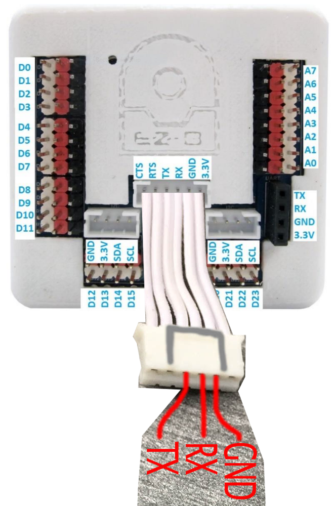
You don't need to purchase another camera. You can connect the USB UART like so...

USB UART    CAMERA TX                RX RX                TX GND            GND +3.3             +3.d

I don't think you need the camera's RTS connected, so hold the camera RTS to GND.

If you have more issues - ezrobot has excellent support on their Contact Us page. They'll be able to help you with their product.

Also, what do you mean by "arc sees the camera port"? Are you saying the camera device robot skill sees the com port? not the Connection control

#9  

Yes the camera device skill sees the the comport.

PRO
Synthiam
#10  

Just make sure the rx is connected to tx and vice versa

#11  

Well DJ, I tried again today no luck I will reach out to EZ-Robot and see if they can help.  I have tried two different USB/TTL's both windows device manager seems to think are working and using the correct drivers.  I have ordered the JSP-PH connectors and will make a cable and try these USB/TTL's on the EZB V4 to the LattePanda maybe they are bad.

Part of the issue is I am MAC user and only use windows at work where we have no access to really do anything with windows setting and such. So some of my issues is my lack of Windows knowledge.  Also just as an FYI if you take a good look at the pictures on the link you sent me they are using the wrong pins on the camera cable based on the port pin outs on the EZB and don't have the TX/RX reversed on the TTL. https://www.ez-robot.com/learn-robotics-serial-usb-connectivity-ezb-smart-robot-controller-and-iotiny.html

PRO
Synthiam
#12   — Edited

The tx and RX need to be reversed. Transmit sends to receive. Receive receives from transmitting. That link demonstrates how to connect an EZB to a USB UART, not a camera. But it's the same idea - however, because the cable is on the opposite side, the wires will be reversed.

Check your device manager and make sure the USB UART devices don’t have yellow marks beside them. Sometimes they need a driver even though they show as com ports.

I've followed that tutorial for all of my ezb uart connections, and they work fine. Recheck the link. You need tx connected to RX. And RX connected to tx. And gnd. You always need a gnd, so the device's voltage has a reference.

PRO
Synthiam
#13  

Here, this might make more sense to you to see that they are not backward and the documentation is correct. I created this image for you using photoshop and the available photos from the links.

User-inserted image

PRO
Synthiam
#14   — Edited

Or maybe this one makes even more sense because I put the connectors on both sides.

User-inserted image

#15   — Edited

The second picture would be correct if that was how shown.  I was looking at it as the cable being plugged into the EZB which would make it backwards. Because in my case the camera was hooked to the other end already.  In these pictures the RX/TX are also not reversed even the picture they showed of the TTL does not have them reversed.  I guess my point is the connection info just was not clear on that page to me.  But then again I am not the sharpest tool in the shed.  LOL

PRO
Synthiam
#16  

Yeah i agree - the context on their page is a little misleading. If they had a diagram like i photoshopped, it would make more sense.

#17  

Ok I have created the cables and been able to make them work on my EZB V4's with my LattePanda using the USB/TTL's but my IoTiny will not work. When I connect to it over wifi and go to its web config page there is no option for USB connectivity like there is with the EZB4's. Is this normal?

PRO
Synthiam
#18   — Edited

The IoTiny does not have USB capability. I believe it's because the TX pin on the IoTiny's micro is used for communicating with the audio DAC converter.

You could use an Arduino micro if you need a small form factor - and they're only a few dollars each and have USB connectivity.

#19  

OK Thanks for clearing that up for me my I just wanted to make sure I was not doing anything wrong.  I was planning to use the IoTiny's in the arms of my Inmoov projected but I guess that is not going to help.  I am open to any recommendations you may have on that.

PRO
Canada
#20  

I had a thought about the camera being connected to a UART to TTL USB adapter. The camera communicates at 3.3Mbaud, most USB-TTL chips don’t run that fast. The FTDI chip is the fastest at 3.1Mbaud.

I also wanted to mention that when using a UART-TTL adapter with the camera you’ll still need 3.3V to power the camera.

The camera needs 60-80mA for power and while the FTDI chip does supply 3.3V with its internal regulator, it’s limited to providing only 50mA. So a external 3.3V regulator would likely need to be connected to the USB 5V.

I purchased some FTDI FT232RL based USB-TTL adapters and received them today. I’ll do my best to test them out with a camera today/tonight.

#21  

Quote:

I purchased some FTDI FT232RL based USB-TTL adapters and received them today. I’ll do my best to test them out with a camera today/tonight.
Jeremie,  please let me know if you get this working.  If you do get it working please provide all the details because I really need this solution.  I know when you are hooking up the EZB4 to the USB/TTL you to set the baud rate to like 230400 or something I don't know if that would need to be the same for the camera.

PRO
Synthiam
#22   — Edited

The camera RTS and CTS pins are...

Quote:

SetIODirection(GPIOA, GPIO_Pin_11, GPIO_Mode_AF, GPIO_PuPd_DOWN); // CTS GPIO_A11 SetIODirection(GPIOA, GPIO_Pin_12, GPIO_Mode_AF, GPIO_PuPd_DOWN); // RTS GPIO_A12

The IoTiny EZB RTS pin is 

Quote:

[UART_2_RTS] = { GPIOA, 1 }, // CAMERA software RTS GPIO_A1

The EZB RTS pin is

Quote:

[UART_2_RTS] = { GPIOA, 1 }, // software RTS GPIO_A1

When the EZB/IoTiny lowers RTS, the camera can send. That means you'll have to hold either RTS low or use the flow control on the UART USB adapter. I would hold it low because there's enough buffer on the PC that it won't matter.

You can see how the EZB lowers and raises the RTS gate for data...


    MicoGpioOutputLow(UART_2_RTS); // open the gate
        
    uint8_t cntr = 0;
    while ((UART_CAMERA_BUFFER_LENGTH - DMA_GetCurrDataCounter(DMA1_Stream5)) < context->flashContentInRam.micoSystemConfig.ezb_cameraOnePacketSize) {
    
      mico_thread_msleep(10);
      
      cntr++;

      if (cntr > 50)
        goto EXIT;
    }

    MicoGpioOutputHigh(UART_2_RTS); // close the gate


#23  

DJ,  I am sorry but I am not following your comment.  Are you saying you can use a UART on the IoTiny to connect the camera to?   Because I this time I am just looking for a way to connect it to the LattePanda USB port and make it work.  I still have not been able to make that work.  My TTL's seem to work with the SCB and EZB4's but when I hook the camera up like you a pointed out it does not seem to work the Device Manage says everything is work ARC sees the com port but the camera skill does not work with it.  Maybe I am doing something wrong.

PRO
Synthiam
#24   — Edited

You can connect any of the EZ-Robot cameras to the iotiny. There's a camera port on the IoTiny to connect their cameras. If that's all you need, connect the camera to the IoTiny. The information I provided above is to help identify the RTS lines to ensure that isn't trouble during your and Jeremie's hack attempts with the EZ-Robot camera.

But you're also asking about connecting the camera to UART on a PC.  To clarify... Do you want the camera connected to the IoTiny or the PC directly? Because EZ-Robot cameras were made to directly connect to their EZBs (IoTiny and EZB v4). If that's all that is needed, then it's good to go.

If the camera needs to be connected to the PC USB and not the IoTiny, the information I provided above will help. Realistically, since the challenge is not being able to hack something outside of its intended purpose, I'd buy a $10 USB camera from Amazon and call it a day, lol. :)

PRO
Synthiam
#25  

I can't find a video connecting a camera to the IoTiny, but here's a picture of where it connects (labeled Camera). The EZ-Robot EZB v4 also has a similar camera port, which I believe you know because you're using that for USB PC connectivity. The IoTiny camera port doesn't do USB connectivity because of some hardware limitations.

User-inserted image

PRO
Synthiam
#26   — Edited

Here you go - this is a good option if you need a low cost small USB camera: https://www.amazon.ca/Camera-Module-Interface-HBV%E2%80%91W202012HD-Android/dp/B08MQJVY8T

It's $13  User-inserted image

#27  

Quote:

You can connect any of the EZ-Robot cameras to the iotiny. There's a camera port on the IoTiny to connect their cameras. If that's all you need, connect the camera to the IoTiny. The information I provided above is to help identify the RTS lines to ensure that isn't trouble during your and Jeremie's hack attempts with the EZ-Robot camera.

But you're also asking about connecting the camera to UART on a PC. To clarify... Do you want the camera connected to the IoTiny or the PC directly? Because EZ-Robot cameras were made to directly connect to their EZBs (IoTiny and EZB v4). If that's all that is needed, then it's good to go.

If the camera needs to be connected to the PC USB and not the IoTiny, the information I provided above will help. Realistically, since the challenge is not being able to hack something outside of its intended purpose, I'd buy a $10 USB camera from Amazon and call it a day, lol.:)

OK I am sorry I was not making myself clear.   I know how to connect the camera to the IoTiny and that works ok with the IoTiny connected by wifi.  To improve performance I want to a wired connection to my LattePanda's USB2 port using a TTL and EZB Camera rather then purchasing another USB camera.  I hope that clears things up.  Thank you for the link to the USB camera!

PRO
Synthiam
#28  

Ah, okay - so back on the EZ-Robot camera to USB. So if that's the case, then the information I had provided was about the RTS pin because the camera will not transmit unless the RTS is low.

But as Jeremie pointed out, while the EZ-Robot camera is UART and will work with a USB adapter, it is 3,333,333 bps. Most USB UART adapters might not support that speed. The thing is, with the massive number of USB cameras, the EZ-Robot camera was never designed to be connected by USB. It's a camera UART intended for the EZ-Robot EZB v4 and IoTiny. Your hack "might" get it to work if you can find a UART USB adapter that supports 3,333,333 bps.

But I think you'll be better off with that USB camera. :D

#29  

OK DJ another question if it was you would you use the IoTiny and camera over a wifi connection to ARC or a USB camera connected to the LattePanda?

PRO
Synthiam
#30   — Edited

Usb all the way. I’m not one to hack something when there’s a perfectly good component meant for the job. I value my time to be building and programming.

I wouldn’t use an iotiny either. Because it doesn’t have usb capability.

id just use the ezb v4s. And if I needed a small controller for the head, I’d probably use an ardunio or maestro from polulu now that there’s a skill for it.

you can get a polulu maestro that does 6 8 12 or 24 servos etc.

oh ps, I shouldn’t add that another reason to use usb camera. It means one less thing to diagnose. If something goes wrong, it’s nice to know you won’t have to worry about the hack job on the camera. All the little things add up when stuff doesn’t go right haha

#31  

Ok DJ I here you I will be ordering a USB camera and I will save the IOTiny for another build.

I am going to use the LattePanda in the head and the EZB4 for the rest of the build.  I may use something else.  For the hands but I need to get to that point in the build.   I really would like to develop a better hand for my build if I can that may require more servos then the current design.

DJ I also really appreciate all your feedback and wanted to make sure I thanked you.

PRO
Synthiam
#32  

Anytime. I am curious with Jeremie’s findings. I remember him and I did it before with our inmoov and an ezrobot camera. He had to find a uart usb that worked for high speed.

although you could make your own with an stm32 lol

actually an arduino could do it if it has hardware uart. An esp32 for sure cause it’s based on stm32

PRO
Synthiam
#34  

Herr ball - that’s awesome. Thanks! I started remembering that conversation with Will soon as I clicked haha. That’s an adapter that will work :)

PRO
Canada
#35   — Edited

Thanks @Herball, I wasn’t able to get to testing last night so you saved me the time! I completely forgot about that thread.

It looks like the PL2303HX is the UART-TTL adapter is the best bet, since it’s the fastest. Will posted a great diagram too.

PRO
Canada
#36  

Hello @smiller29 I thought of something that might not be clear to you. I work for EZ-Robot and am addressing your problem here instead of by direct email. Addressing it here allows us to continue the ongoing conversation and share the knowledge with all those interested :D

I ordered a PL2303HX UART-TTL adapter to test out Will's solution. I should have it in a day or two.

#37   — Edited

Jeremie, and everyone else thank you all for this effort on this subject it is much appreciated.

DJ,  you made the below comment:

Quote:

id just use the ezb v4s. And if I needed a small controller for the head, I’d probably use an ardunio or maestro from polulu now that there’s a skill for it.

you can get a polulu maestro that does 6 8 12 or 24 servos etc

I have installed the EZ Arduino Leonardo firmware on the LattePanda for the 8 servo's in the head.  Do think this will be a problem?   I am planning on using two EZB V4's for the rest of the robot connected by USB/TTL's to the LattePanda.  Although I may want to put something small small in each arm connected by USB to control the hands just to try cut down the wires running into the arms.  But time will tell what's going to happen with that.

PRO
Synthiam
#38  

That's a great solution. I forgot the lattepanda has an arduino built-in.

#39  

DJ,  I know this is off topic but can I also use this to control the NEOPIXEL RING (16Bits WS2812 5050 RGB LED Ring) on the robot with all the servos for the head without having to purchase another controller?  Please forgive me if I am asking stupid question but this is all new to me.

PRO
Synthiam
#40   — Edited

I'm not sure on that one. I think there is a robot skill for the neopixel ring. Could you take a look and see what it needs?. I feel like neopixels require the Arduino processor to be dedicated due to the speed that they operate at. I don't have any experience with neopixels, so I won't be much help in that area

PRO
Canada
#41  

Yep, remember when we built the neopixel blaster @DJ? There was nothing we could do with the EZ-B to get the timing that fast. An Arduino (or equivalent) controller was needed to produce the signals for the WS2812B LEDs. I believe Dave Cochrane built a skill that incorporates an Arduino and Neopixels.

#42  

Well it looks like I will have to purchase an Arduino uno to deal with this.  And yes I found the skill for it thank you guys.  This project just keeps getting more and more complex and costly.  I guess that is expected.

PRO
Canada
#43   — Edited

Hello @smiller29, well I ran into a speed bump. The PL2303 uart-ttl adapter I ordered was the HX 'A' version (PL2303HXA) which as it turns out didn't get driver support in Windows 10. I had no idea that some chip versions didn't get driver support for Windows 8 and 10 (I guess some of the chip versions are legacy products) It seems like they come out with a new chip version almost every year!xD Here's the chip version Windows 10 support list:

User-inserted image

Now I have to order another one. Learn from my mistakes I guess xD

#44   — Edited

I ordered two PL-2303HX that is said to work with Windows 10 32/64 bit so I hope it works.  I hope your test works.  I ordered a USB Camera but I am not sure it will fit in the chest where I want it like the EZ-Camera will.

PRO
Canada
#45  

I hope they are the D’ version, cross your fingers

#46  

Quote:

I hope they are the D’ version, cross your fingers
Well Jeremie,  the ones I got also did not work the part description was not correct. So I am sending those back tomorrow.

PRO
Canada
#47  

Hey @smiller29 I received my PL2303TA USB-TTL adapter today and I've done a bit of testing with it. It connected to my laptop as soon as it was plugged in and appeared as a COM port. Using the serial terminal (PC) in ARC I was able to verify that it was communicating with local echo and that it could communicate at 3.3Mbaud. It is rated to go up to 6Mbaud max. Unfortunately, I can't seem to get images to come through with the camera yet but I'll press on tomorrow.

PRO
Synthiam
#48  

Local echo doesn’t use the adapter. Local echo means just display the characters you typed

to test a true echo, you’d need to connect rx and tx together in the uart

PRO
Canada
#49   — Edited

Lol, that’s what I meant. EX: I sent U and got back UU. RX and TX were jumpered

PRO
Synthiam
#50   — Edited

K that would be a remote echo - even though there's no remote host but it's going through the wire. If Local Echo is checked in the terminal program, that means just display the character that were typed back to the user. Terminals used to need that option because back in the day different services/bbs may or may not echo the character back at you. So you'd have to turn it on or off in software... or you get douubbllee kkeeyy ssttrrookkeess!!

And you saw UU because the first U was yours, cause local echo was checked. The second U would have been from the wire.

User-inserted image

PRO
Canada
#51   — Edited

Sorry man, I understand how it works I guess I used the wrong terminology.

PRO
Synthiam
#52  

Do you have the rts connected? Also - does the led flicker? I think it flickers with every packet or something. So if it's not flickering then it isn't sending. The camera won't send unless the rts is held low.

PRO
Canada
#53  

Yeah I held the camera side RTS low, and swapped TX/RX back and forth just to make sure I didn’t get it wrong. I also provided 3.3V and GND to the correct pins. I’ll look at it more tonight or tomorrow.

PRO
Synthiam
#54  

Hmmmm. Check with the camera on an ezb and see if the led blinks. That will let you know if you can see if it’s transmitting

PRO
Canada
#55  

Well, I am at a loss. I have tried the following but I can't seem to get the camera to communicate over the USB-TTL adapter:

  • Confirmed PL2303TA USB-TTL adapter is rated to a maximum 6Mbaud of communication speed
  • Confirmed that the USB-TTL adapter is working using remote echo
  • LED on the camera is on but doesn't blink, this is normal for V2 camera, I believe only the Camera v1 blinked during communication
  • I confirmed that the camera does work by connecting it directly to an EZ-Bv4, double-checked the LED was solid while working
  • Tried multiple V2 cameras with different firmware versions (Green LED versus Blue)
  • Tried swapping TX/RX in case of mislabelling
  • Tried tying RTS and CTS to GND in separate tests
  • Tried lowering the communication speed (COM4:115200) but it didn't have an effect

Here are the two errors I get depending on which way TX/RX are connected:

User-inserted image

User-inserted image

@DJ any ideas?

PRO
Synthiam
#56  

The first msg implies that the tx and rx are wired correctly. But the message appears that it’s missing the header. So either

  1. the baudrate isn’t supported and the data is unreadable and garbled

  2. there’s too many missing because the converter can’t keep up so the packets and the header can’t be found. or there’s too much noise on the line. Although you’d think at least one header would be detected

#57  

Following post #33 link, DJ states not to put the baud rate in as it would default to 3,333,333 bps . Did you happen to try that? Just a guess on my part.

PRO
Canada
#58  

Thanks guys! I’ll try removing the wire on the adapter side to limit noise. This will also give me access to the RTS pin on the adapter side. I forgot to mention that I also tried switching the baudrate in the device manager to match the lower baudrate when I entered it manually in the camera skill.

@Herball yeah I was mostly testing at the default speed (ex:COM4) without the additional baudrate added.

PRO
USA
#59   — Edited

Hey guys still working on Guardians 3 so I am away from my computer/robots/parts etc. And I have brain rot, so I've gone back over the old thread to see if anything has jogged my memory.

-I went with the revision "D", the PL2303HDX, because I knew it would be running on Win 10 (for drivers).  -Voltage supplied was 3.3v -Post #36 was the final wiring diagram that I got it to work. -Once I had a video feed I got "ripped frames" where the feed seemed to lose sync between frames.(post #37) -That was resolved by moving to a new computer and therefore a newer USB socket. All my issues went away after that. Not sure why that was. (post #48)

I have these in all my robot heads and they work great. Hope this helps?!

PRO
Canada
#60  

Thanks Will! I appreciate you taking the time to chime in!

Can I ask you if you are using the latest version of ARC with the PL2303HXD, just to rule out if there's something in the software that's different?

Well I'm starting to suspect it's my Laptop at this point. I have tried force switching different COM ports, verifying that I truly have 3.3V powering the camera (I do), tried another USB port, did continuity checks on all the connected GNDs (all good), tried 2 different FDTI FT232RL adapters (at lower baudrate COM8:115200), and tried messing around with connecting RTS/CTS to GND on the adapter side, I can't seem to get it to work. Is there a setting I'm missing somewhere maybe? Do I need flow control on?

PRO
Synthiam
#61  

Jer - I checked, and there hasn't been a change to the uart video code in years. The code also works because it's the same code that the TCP video uses pretty much. The message you're getting about the buffer filling is that the header cannot be identified because the data must be garbled.

Changing the baud rate by specifying it (i.e., COM8:11500) will never work. This is because the camera transmits at 3,333,333 baud, not 115,200.

PRO
Canada
#62   — Edited

Quote:

Changing the baud rate by specifying it (i.e., COM8:11500) will never work. This is because the camera transmits at 3,333,333 baud, not 115,200.
We were able to get 115200 baud to work, proof is in the video you and I did when we were testing for Will. The frame rate was just much slower. Or was this a custom version of the software that allowed it?

PRO
Synthiam
#63  

That was a custom firmware

uart serial requires both parties involved in the communication to have the same baud. The baudrate is how fast the two devices transmit and receive. If one is not at the same baud as the other, there’s no way either can understand each other.

this is because one is speaking a different speed than the other. They need to speak the same speed or it’ll never work.

what’s happening with your setup is there’s data, but it’s skipping bytes or being garbled. That could be due to a slower USB port or the uart usb converter.

the ARC parser is looking for a header which is EZIMG. It needs to find those 5 characters. Then the next 2 bytes is the packet size as an unsigned int.

if the data is missing bytes or garbled, it’ll never find the text EZIMG and therefore just continue receiving what ever data is on the wire.

If you want to test it at a different baud rate, then use an esp32 cam with the firmware I made a few months ago. There’s a version of the esp32 cam that replaces the ezrobot camera and can connect directly to an ezb. But rather than connecting it to an ezb, just connect it to your uart adapter.

In that firmware, you can change the baudrate to what ever you want including 115200

PRO
Canada
#64   — Edited

Understood, I thought the camera might have a variable baud rate, my mistake. I forgot to mention that I also shortened the wires on the PL2303TA but it didn't seem to have any effect. I also did verify that it was actually communicating properly using an Arduino Pro mini. I was able to program it. At this point, I'm going to see if I can get my hands on a PL2303HXD or equivalent or try with another computer.

User-inserted image

*Edit: Yeah thinking more about it, I feel that it's likely the advertised baud rate of the PL2303TA is likely not up 6Mbaud, or maybe it is under very strict circumstances. The PL2303GC and PL2303HXD are rated to go to 12Mbaud so that's much higher than 3.3Mbaud, I have much more faith that those will work.

PRO
Synthiam
#65  

when you tried the rx and tx together for the terminal test, did you set it to 3333333 baud?

PRO
Canada
#66   — Edited

I hadn't done that, I believe I tried 3,000,000 and it worked. Anyway, I just tried the PL2303TA at 3,333,333 baud now and it worked with RX/TX jumpered.

PRO
Synthiam
#67  

Try the esp32 cam firmware and modify the code for a lower baudrate

PRO
USA
#68  

Sorry, Jer just had the time to respond. You might be right, the two heads in the science museum in Kuwait are on much older ARC software. I can't remember if the heads at home are using this setup, I won't be able to check for another 2 months.

Hopefully, you have better luck with a newer laptop like I did, or get yourself the PL2303HXD or a completely different brand. Although I did have trouble finding one that was that high of baud. (maybe more avail now i think that was back in 2017/2018?)

Good luck!

#69  

Jeremie,  and the rest of you folks that are working on this question I posted please understand that I would love to know if this could be done, I really don't need this solution anymore because, I followed DJ advice and purchased another USB camera for my current Inmoov build.  I will find another use for my EZ-Camera in some other build.

I just don't want you to pull your hair out on this on my account...

PRO
Canada
#70   — Edited

Well, @smiller29 even though it isn't of immediate benefit I wanted to see this problem through to its end!

After investing in 3 different USB-to-TLL adapters and doing quite the hack to the third one, which was supposed to be a USB-to-RS-232 adapter, today I was finally successful!

User-inserted image User-inserted image

The only PL2303HXD chip I could find available was on an RS-232 adapter so I had to make it work. I removed the RS-232 chip and ohmed out the pads where the PL23203HXD RX, TX, and GND pins went to and soldered on some jumpers. I connected everything like Will did, except that I didn't even need to attach the camera RTS to GND, and it worked right away. All I had to do is to connect to COM3 in the camera skill and the picture appeared. It even looked great! No artifacts. Nice and crispy!

So word to the wise the FT232RL, PL2303HXA, and PL2303TA UART-to-TTL adapters aren't able to communicate at the 3.33 Mbaud needed by the EZ-camera but it seems that the only UART-to-TTL chip that can is the PL2303HXD (and possibly the PL2303GC - untested).

Thanks to everyone who contributed, and Will who originally posted the tutorial!