
Rural Geek
Canada
Asked
— Edited
Servo Amplifier
Hey everyone.
I am putting together a BOM for version 2 of my bot. Its going to be humanoid type of thing. Head two arms and mobile base I am using some ideas from here.
The arms are going to be driven by gear boxes from servo city, and I want to make sure they get what ever power they need. So I am wondering is there a board that I can supply power to and the signal from the EZ-B and plug the servos into the other side?
I am just trying to keep the EZ-B from working to hard and only doing the processing.

Am I right in thinking you want the power to the servos to be 6V (or whatever) and not supplied by the VCC and Gnd of the EZB?
If so, I mentioned a board I made the other day. Very simple too, a small piece of strip board, +6V and ground feeds 2 of the tracks, these then have the servo extensions soldered in to the tracks also (from the female socket end), the male plug end is untouched and plugs in to the EZB for signal.
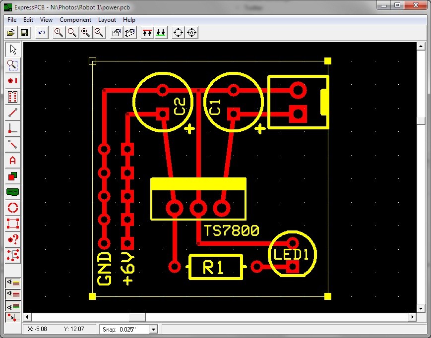
I did draw a PCB design for this (with 6V regulator) but it's at work and I wont be back until Monday. If it's unclear I will try to sketch it out for you.
If I have misread or misunderstood then ignore that
@Rich.
Yea thats what I was looking for. Dang as soon as I read your reply I was pissed I didn't remember reading that.
its going to come off the same 12v battery so there won't be an issue of floating ground.
I found a place in Ontario that can make PCB's for me but I have to make the drawing for them. What software would you recommend to make a PCB drawing?
Yep nice and simple. I am going to build it with one of my bread boards then see if I can get some PCB's made to clean it up for the final build.
ExpressPCB is great, easy to use and you can even get them to make the PCBs (expensive for a one off though).
If it's 12V you will want a 6V regulator circuit before the strip board, although I'm sure you knew that but others may not I use a LiPo one, but it will work on anything, 5A 6V is plenty for my build. This is the one I use
Just found ExpressPCB software so it looks like it will do what I need it too.
It's also great for schematics too and you can link schematics to PCBs (although I don't but I rarely make PCBs due to the high cost, stripboard, proto board and bread board (anything with board after it) works just fine even if it does look messy with flying wires all over the underside.
ExpressPCB for anyone else who needs it. It's free too which makes it so much better.
Yea thats what I was thinking of finding a already made regulator and mount it. I don't mind having a couple like one or two regulator/supply for each arm.
The reason is I am not sure what its going to take current wise to just run the arms and speed and I just lazy to do the math.