Rob-bot
USA
Asked
— Edited
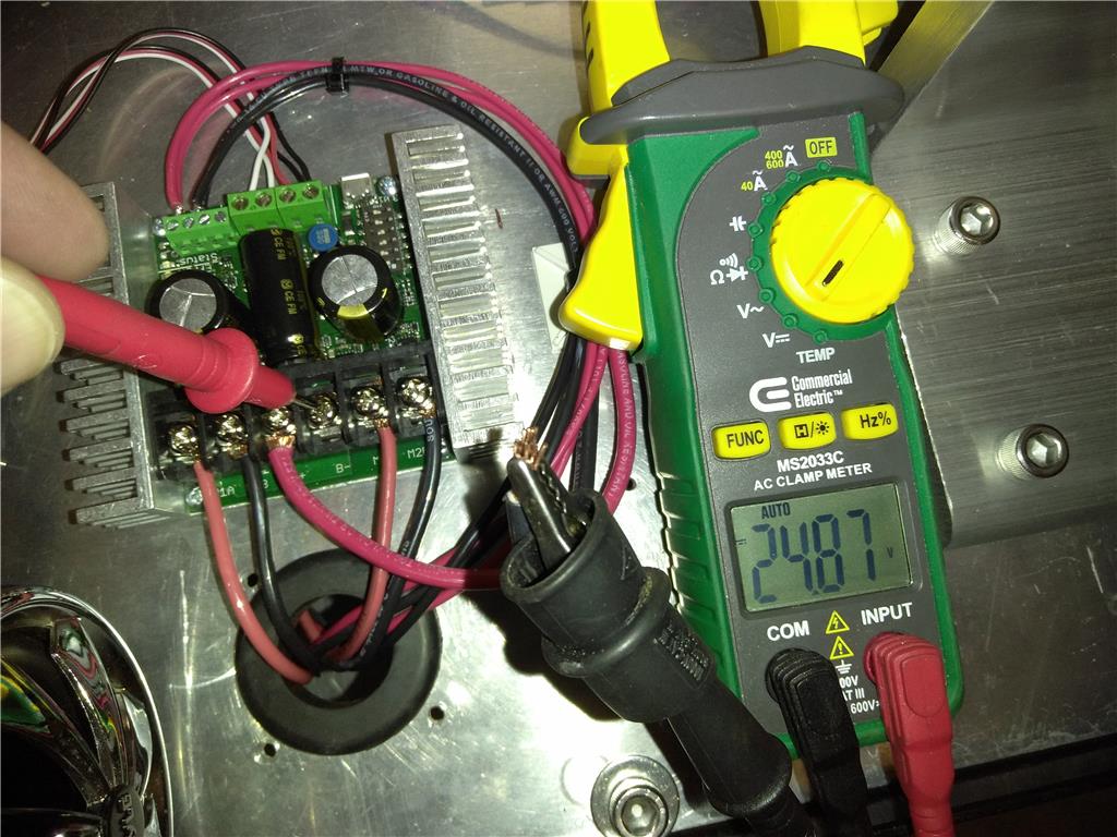
Hi All, I am working on a wheelchair based robot that utilizes 2 24 VDC motors and will be controlled by EZ B V4 controller and a Sabertooth 2X32 motor controller. The problem Im having is that when I hook up the positive 24VDC line to the Battery + terminal I get positive potential through all remaining terminals. So, basically if I put a volt meter probe on the detached negative and the other on and sabertooth controller terminal I get 24VDC, which I think would cause a short. I tried calling and emailing Sabertooth Tech support with no response for a couple of days, so any help at all is highly appreciated ?
Thank you.

Yes, testing with RC, but will soon change to E-Z B V4 once I learn a little more about the controller. I had one switch wrong, so now I am getting RC communication, but noticed the brake is stuck on. In DEScribe I added brakes to P1 and P2 and uploaded, but they are still stuck in the default locked position. Any ideas on this? Thanks
PTP, Thank you for all of your help. I found your answers most helpful, but also appreciate all who contributed too. I will start a new thread later on how to figure out why I cant get the brakes to release, but need to get some sleep first.
Thank God for this forum and its contributors. I hope one day soon I can also help others here too.
I thought a constant voltage to the brake lead was needed to keep them released? I assume it is a safety feature (or dead man switch) to prevent the wheel chain from rolling in case of power failure, user error or malfunction... However, I do believe it is possible to remove the brake mechanism altogether. I am pretty sure some people here have done this...
I've never worked with the breaking feature of the Sabertooth. However I have read a few things about a braking system on power wheelchairs and using a Sabertooth to convert them into a bot.
We know little about your bot and how you have it set up and wired. It sounds like you may be using all the original motors, brakes and wiring from the power wheelchair?
You say you added the Breaks in the Power Output tab in the DE software? Did you set the Turn-On, Turn-Off Delay and the E-Stop delay below the Mode window? You may have to adjust these to get the brakes to work as needed.
Also are you supplying power to your breaks? I've read that the default of a power wheelchair braking system is locked on when there is no power in case the power system shuts down (for obvious reasons). EDIT: (I now see RR mentioned this as I was writing my post. I'd pay attention to what he suggests).
Here is a cut from the the ST 32 manual: In this mode, the power outputs are used to operate electromagnetic brakes. P1 corresponds to motor 1 and P2 corresponds to motor 2. When the motor stops, the brakes activate after the Turn-On Delay. When the motor is commanded to move again, the brakes deactivate immediately, but the motor does not turn until the Turn-Off Delay has elapsed. If an emergency stop is commanded, the brakes will activate after the E-Stop delay has elapsed.
Lastly, if you have rewired to the braking system did you install blocking diodes? If not you need them. If so you may have them in the wrong direction.
Hope this is helpful.
Guys, Thanx for the replies. Yes, the braking system is the original that came with the motors. I noticed people who have the earlier sabertooth models just removed the braking system being those models didn't have that option. I did consider removing the brakes but are afraid the robot may roll freely on a hill etc... I think you guys are right about I just need to adjust the settings, but not sure why a diode is necessary? Can you explain please. Thanks.
Two things happen with the diodes, they allow DC to get to the brakes in forward/reverse and they don't allow current back to the motors from the brakes. The diodes are required and the breaks will not work correctly without them.
Dave, I see what your saying. I wonder if there are diodes already on the controller for that being P1 & P2 are designated outputs only. As far as the motor leads go, I will have to remove the brake cover to see if their is already a diode installed by the manufacturer. If needed, would 60A diodes be sufficient?
Again, I've never wired or controlled a setup like this and I don't know how you have yours wired. The diodes may not be needed If you have you break wiring completely separate from the motor power feed and going directly to the sabertooth 32's p1 and p2. The drawing I posted show how to add the needed diodes if the breaks and motor share the same power feed from the sabertooth.
The size of the diodes need to be sized to the amount of amps that this part of the circuit is passing. That usually depends on the amp draw of all devices added together. You also should use fast switching diodes.
Good luck.