
Rob-bot
USA
Asked
— Edited
Sabertooth 2X32 Controller Voltage Question
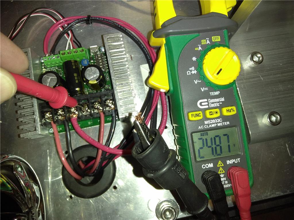
Hi All, I am working on a wheelchair based robot that utilizes 2 24 VDC motors and will be controlled by EZ B V4 controller and a Sabertooth 2X32 motor controller. The problem Im having is that when I hook up the positive 24VDC line to the Battery + terminal I get positive potential through all remaining terminals. So, basically if I put a volt meter probe on the detached negative and the other on and sabertooth controller terminal I get 24VDC, which I think would cause a short. I tried calling and emailing Sabertooth Tech support with no response for a couple of days, so any help at all is highly appreciated ?
Thank you.

@Rob-bot,
If i got the right picture:
IF you you read 24 volts on your voltmeter is not equivalent to have a short circuit on your board.
Your voltmeter is closing a loop, asfaik Sabertooth does not have a power off button, so the electronic (h-bridge) is reacting to the energy flow.
If you want to check for a short circuit switch to Resistance (ohms) and measure the resistance between Sabertooth's bat(-) and bat(+) , if you get zero, or a low resistance something is wrong.
I would add a fuse between the battery (+) and the sabertooth (+), if something goes south, the fuse blow up and you protect your setup.
I agree with ptp that fusing is critical in protecting your project. However the Sabertooth is a whole different animal. Dimension Engineering suggests not placing a fuse between your power source and the Sabertooth. Here's an explanation direct from the horse's mouth: If this is more of a hobby project instead of an industrial product, most people do not use fuses. The Sabertooth has built-in current limiting.
We prefer that you fuse the motors rather than the battery leads, or if for safety reasons you need to fuse the battery that you do it at a much higher current than the motors. The reason is this:
Because Sabertooth is a regenerative driver, it relies on having a battery to put regenerated energy back into when you command a stop (and at other times). If you draw enough power to blow a battery fuse, all of a sudden the Sabertooth has nowhere to put the energy. It will see the fault, though, and try to stop the motor. It doesn't, however, have anywhere to put the energy (the mechanical energy of the vehicle and the electrical energy carried in the windings and the caps). So blowing a battery fuse will sometimes kill the driver -- which we would replace under warranty, but it's still annoying for all parties.
The better way to do it is to fuse the motor leads. If a motor fuse blows, the motor will freewheel, the Sabertooth will sit there contentedly, and the only thing you will have to replace is the fuse. A very large fuse (100 amps) on the battery lead will protect the wiring in the event of a battery lead short or motor driver failure.
PTP and Dave S.,
Thank you so much for you fast replies. I will take both of your advice and check the ohms between B+ and B- and add fuses to the motor lead. What size fuze is appropriate for these motors/controller? I'm at work now, but will check 1st thing in morning when I get home. Thanks again.
@Rob-Bot,
I would put 100 amps between the battery (+) and the Sabertooth.
The high value will allow the regenerative circuit to work and protect your setup.
PTP, I left the OEM battery harness, which has a 60A blade style fuse, change to 100A? What about the motor lead? What size fuze do you recommend for each motor? Thanks.
@Dave
Thanks for sharing the info, i got curious regarding the "regenerative driver" i need to add to my list.
I can't find a Sabertooth schematics, is it public ?
Regarding setups with high amps, i pay a lot of attention to the wiring and i add fuses to extra protection.
One of my bots has 4 x 12v 9 A SLA batteries in parallel, i added a 10 A fuse between each battery and the main circuit.
Both motors (left & right) have a fuse of 8 Amps.
If the bot gets stuck blows the motor fuse, it's annoying but broken fuse is better than a fire or short circuit.
To prevent blowing up the motor fuses, i have a micro-controller monitoring the motor controller amps when the value is too high cuts the motor power.
It seems the Sabertooth does that, although they recommend a motor fuse.
Don't ignore the safety recommendations.
If you place fusing between the motor and the sabertooth then you would be matching the amp draw of the motor. I also add about 20% or so for overhead so you don't blow the fuse if you reach that full amp draw. You're running a Sabertooth that is rated for 32 amps plus your overhead = 40amp fuse.
Edit: Woops. Here's the correct answer:
Peak motor amp draw + 20% overhead = correct fuse size.
@ptp, I don't ever remember seeing a drawing of the sabertooth's inners. They probably want to protect that information.
60 Amps is OK, if blow up you need to check what happened, if is the regenerative driver you need to go up.
Sabertooth has a built-in current limiting, i presume the model 2x32 will cut the power if try to pull more than 32 Amps (continuous).
The motor fuse should be aligned with your motor's max recommend amps.