Andy Roid
Relay Driver Using An Arduino To An Ezbv4
Hello All,
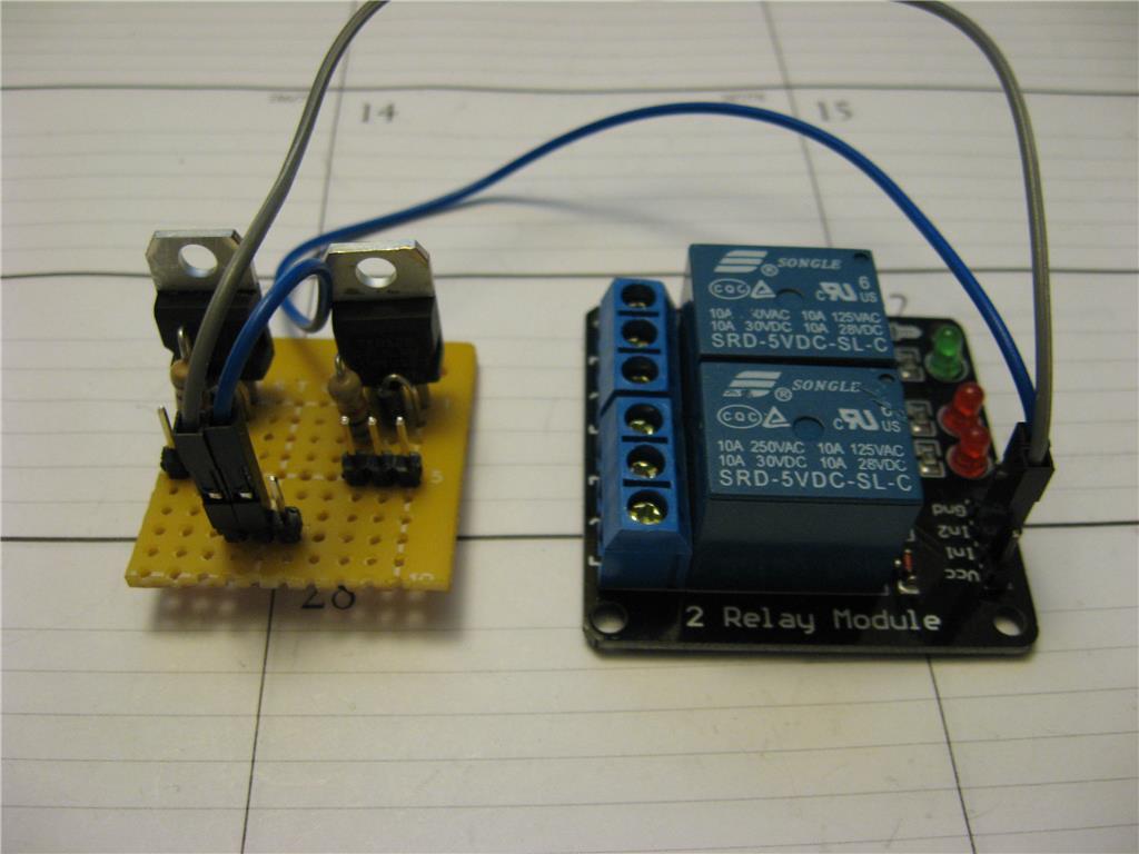
I have an 8 relay 5volt relay board, (compatable with Arduino) which I want to drive from my EZBv4. I have made a script to run the ports D8 and D9 on and off for testing. The problem I have is the relay turns on but fails to turn off. I am using an ezb regulator to power the relay board. I thought I power draw might be too high so I changed to a two relay board of the same spec. I have the same problem with this board.
I see some other people have similar issues driving relays from their ezb's. Any suggestions? I never felt a full answer to the problem was made. I hoped additional hardware wasn't needed. I am beginning to consider building a transistor switching circuit to go between the ezb and the relay, but felt I shouldn't need it. I also considered using an Arduino?
I always thought a relay should be able to be driven direct from the ezb as described in the digital port spec..
Can anyone help.
Ron R

The relay board should have a transistor switching circuit (or similar) as part of it. Most of the ones I've seen do.
Without info on the board/boards you are using it's guesswork. Provide the datasheets for the boards and someone may be able to give you the full answer. I would guess that it's due to lack of info that's lead you to not having a full answer.
This problem (with the relay you have) has been mentioned here before... The only one I got to work so far (plug and play with the ezb) is this one Brick Relay...
Here's a link to a similar thread on relay issues... Relay issues...
Thanks for the reply guys.
I have two boards which meets my needs. I prefer not to go out and buy more boards and wait for them. I assume if I build a transistor switch circuit the problem will go away.
@ Richard R
Richard, would it be worth hooking up to an arduino? I have an old Uno lying around.
Ron R
I forgot to mention this is a static robot (My project Madame Ninndo) so power sources (3.3 or 5 vdc) won't be a problem.
Rich also created this: https://synthiam.com/Community/Questions/3050
If you need to use a relay, it should always have a transistor to toggle the position. If you see it say arduino ready or arm ready, 15-20mha is still a lot for a micro to source. You could reverse the connectivity and sink the relay from the ezb, but I wouldn't recommend that either - specifically since you're asking to connect 8 to the ezb!
Follow rich's tp tutorial and create a driving circuit for the relay - or maybe you don't need a relay at all and can do the job with the tp transistor from rich's tutorial.
Again, it depends on the boards. If they already have a transistor circuit on them then where's the point in adding another one? It also comes down to what the relay requires to energise and de-energise. This is where datasheets come in handy and would answer the questions immediately rather than guessing and the trial and error approach or assuming which could possibly damage both the relay and the EZ-B.
I also can't see how any of the above has yet solved your question but that's just something else I touched on a while back...
If the relay breakout has a transistor to toggle the relay, it should be 100% compatible with ezb. This is because the voltage required to trip the relay is from the transistor and not the micro. Wouldn't matter if the micro was 3v
Hi Rich and Dj,
Thanks for your responses. I am looking for the data sheet for the relays. The information you, Dj and Richard R gave me, made me think I must know more about the relays. I believe they are not switched using transistors.
The relay blocks Richard R suggested will fix my issue, and I will be getting them on order, but I would like to continue experimenting to try to get the relays I have working. My project at this time only requires three relays. I will need more in the future.
As Dj mentioned, I want to make a transistor switch anyway so I may try and see if it can trip the relay. I will post how I make out. My project deadline is coming quickly so I need to continue forward.
I thank you for your tutorials and I need to be sure to not forget to refer to them more.
Thanks again to All,
Ron R
Awesome, Ron. Once you are comfortable with the information from this experience, feel free to make a user tutorial in the learn section.