
MovieMaker
Question About Ezb4 Before It Comes In:
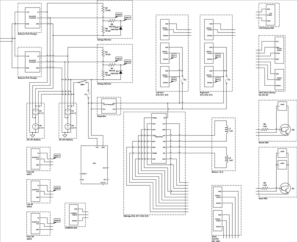
I have now two 12v batteries on my Sunshine robot. I plan to hook up the EZB4 which will allow the 12vdc to go to the bus. Then I will regulate EACH individual device. They will also get the same 12v which will be regulated to the 6 or 7 volts they need to operate. I have them already wired and ready to receive the EZB 4.
I plan to move the servos and then park them at a place and release the juice going to them.
Hope that will work. I have her brain ready to go now.
I will then add sensors. She is hooked to the 10 servos now, but no sensors. I have to figure a way to get the camera on top of the head. That is what I liked about the wireless camera on EB 3. It was easy. Just find a digital port and hook it up to turn it on. Now the other situation has me a little bit concerned. I did not build the robot to take apart. In fact, I barely got it together as it is. There is NO room to work in the head. So, that is going to be a challenge, I suspect.
I have many sensors, IR,PIR,Ultrasound, Compass, microphones for direction, photo sensors, and many more.
I plan to operate the wheelchair motors through the recommended Sabertooth on the EZB 3.
I wonder if I can hook the camera up wireless without having to run the ribbon cable to the camera.
I guess you understand what I mean.
Wish me Luck!

So, what is your question?
All of the above. Is it going to work?
Mainly the way I have it wired.
I have a camera question in there. and also would like advice on routing the wires.
That's a seriously difficult question for other people to answer as you have made a custom project, unique in most ways...The short answer is sure, if your skilled enough... The better answer is... Doesn't look like you're doing anything wrong.....
Well, that is good to hear. My biggest problem ever is that I started building robots in 1975. I could see back then and my hands were not arthritic. Now, it is a challenge to say the least.
All you need to worry about is voltage regulating everything you plug into the board for it's specific voltage requirements... Servos at 6V, sensors at 5v, etc... Analog is at least pretty much plug and play... albeit that the output pins are 3.3V not 5V... You will need to make sure your PIR detector can run on 3.3v... or anything else you plug into the analog ports for that matter...
That is more of what I wanted to hear. I will also accept suggestions from other members of the group. Thank You very Much!
You can use another wireless camera instead of the EZB4 one... However, I don't see any way of making the ezb4 camera wireless... Best thing would to either locate the ezb4 in the head near the camera, use another camera or be the first one to find extension jst cable for the EZB4 camera...
... DJ has mention that a Wifi camera is coming to the store at some point....