
Asked
— Edited
My turn to ask a question for a change
My MMA7455 arrived today but I'm struggling to get them to register anything when connected. Just wondered if I had it connected up right or if I need to do anything extra.
My wires are about 1" long, connected to VCC, ground, SDA and SCL on the MMA and on the EZ-B.
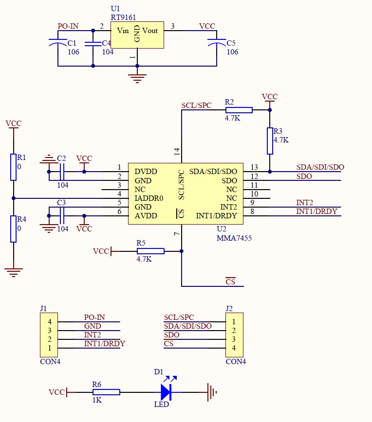
I'm using a simple breakout board which uses the MMA datasheet here.
Schematic of the breakout board is;
Update/Edit: I think I may need to set the CS pin high, i.e. 5v. Is that correct? I don't want to fry the EZ-B or the MMA.

Edited to remove useless links.
Alan
Thanks, but that's for serial connection, although it did make me think that perhaps I need to try putting CS to ground, but alas no luck there either.
@Rural, no rush, I never intended to use these on the robots, I only got them to play with them and see if I can do something cool with them. I may get in touch with the people who made the breakout board and see what they say although they are Chinese which doesn't help as far as the language barrier is concerned.
FYI, it's made by LC Studio
If R1 and R4 are really 0 ohms that would short VCC to ground. Does the D1 led come on?
Yes, D1 lights up.
I wouldn't have thought their circuit was wrong, they must have sold a lot of these without problems. I'm assuming I either need to connect it up correctly using the 8 pins on it or I need to initialise it - or the I2C address for the control is not the same as the I2C address of this particular module.
I found this
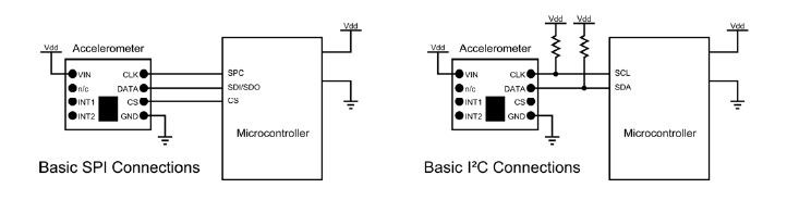
For basic I2C you leave the CS pin floating as its already pulled high in your circuit diagram. Note also the VDD and GND need to be common with the microcontroller or in this case the EZBYeah that's what I thought, and it's what I have. I think the pullup resistors are also on the breakout board?
The board is connected to the I2C bus, vcc to vcc, gnd to gnd, scl to scl and sda to sda. I really can't understand why I'm having problems getting it working, it should be working out of the box...
You are not wrong Rich. I would guess it needs initializing 1st
@Rich sorry gave you wrong link in previous post, as it dealt with the compass connections
Although that uses SDA & SCL inputs also, to get that to operate I connected both of these to GROUND using 2 x 10k resistors ( not to the + rail ) I am open to correction but I believe others have used this also to get the compass up and running.What I am saying is it possible it may also work for the accelerometer.