
Asked
— Edited
My turn to ask a question for a change
My MMA7455 arrived today but I'm struggling to get them to register anything when connected. Just wondered if I had it connected up right or if I need to do anything extra.
My wires are about 1" long, connected to VCC, ground, SDA and SCL on the MMA and on the EZ-B.
I'm using a simple breakout board which uses the MMA datasheet here.
Schematic of the breakout board is;
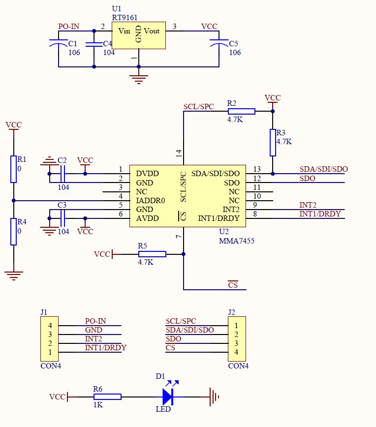
Update/Edit: I think I may need to set the CS pin high, i.e. 5v. Is that correct? I don't want to fry the EZ-B or the MMA.

I'll try the resistors to ground tomorrow although I really don't think they should be needed as it's a breakout board so everything should be taken care of on the board itself, and the schematic shows it is. But if I don't try I'll never know for sure.
I'm still scratching my head a lot over this one though, it should work!.. I can only think that I may need to send an I2C command to set the mode since it has a few modes according to the datasheet, but then again I would have thought the control in ARC would take care of this...
Looking at the Parallex version, the schematic is slightly different but basically the same configuration. I'm starting to think I may have got 2 bad ones after all but I wont give up just yet. Would be really good to hear from someone who has used one though to see if I am missing something.
More for my reference tomorrow when I play more, but also to check that the address of the sensor is 0x1D (correct or confirm if anyone knows).
Hello Rich, hum, did you take a look at page 19 ? If so you will see two errors in your drawing, the first is IAddr0, need to be at Vcc, the second is the output to the I2C bus, one of the out you use is not the good one and they suggest pull up resistors at 4.7K
$1D look like the good adress for me.
You did not take the easiest to deal Rich, lucky you are pretty good in scripting.
Rich and Co.,
I think your chips are bad. I just hooked up my MMA7455 mine up 2 inches wires for SDA and SCL and 4 inch wires for the ground and + and it works perfectly. The little green cursor in the latest version of EZ-B shows up and moves as the bot does.
No pull-up resistors were necessary. I'm working on a balancing bot next and will post a video upon success.
Best,
Bill
@Andre99 it's not my schematic it's the schematic from the manufacturers. I wouldn't have thought it was wrong.
@EEGbiofeedback thanks for the info, that is just what I needed to hear. I'll triple check my wiring, try both of the MMAs I have and try them on both EZ-Bs just to make sure. Thanks.
@EEGbiofeedback can you tell us where you got your board from?
The Parrallax one Rich has a voltage level translator chip on the board and I cant see that on the pic posted be EEGbiofeedback? a pic of Rich's board would be useful. It just connects between pin 13 of the chip and the SDA output. The pinouts on the board seem to be different as well. Great to know it works
This is the one I have...
MMA7455
So its identical then weirdness!
Although this isn't a pic of your actual board though? Looks like it was soldered by a Gorilla (apologies to any Gorilla's reading this)
I noticed that, I'm sure my board has better soldering. I'll double check when I'm home and post a photo of the actual boards, use new jumper wires etc.
It does look more and more like I have 2 bad boards, which can happen I guess if I am extremely unlucky.