winstn60
United Kingdom
Asked
— Edited
 EZ-B V3 Configuration
— Manage EZ-B hardware settings: edit Bluetooth name and apply updates to restore altered configurations.
Try it →
EZ-B V3 Configuration
— Manage EZ-B hardware settings: edit Bluetooth name and apply updates to restore altered configurations.
Try it →

Thank God for that, I thought it was only me who had that happening. Mine was working fine but sometimes it doesn't. I just thought I had wired it up wrong again or it was because I have other I2C devices running too.
I plan to look into this one this weekend to see if I can work out what I've done since it worked and since it stopped working but hopefully someone can give us a clue.
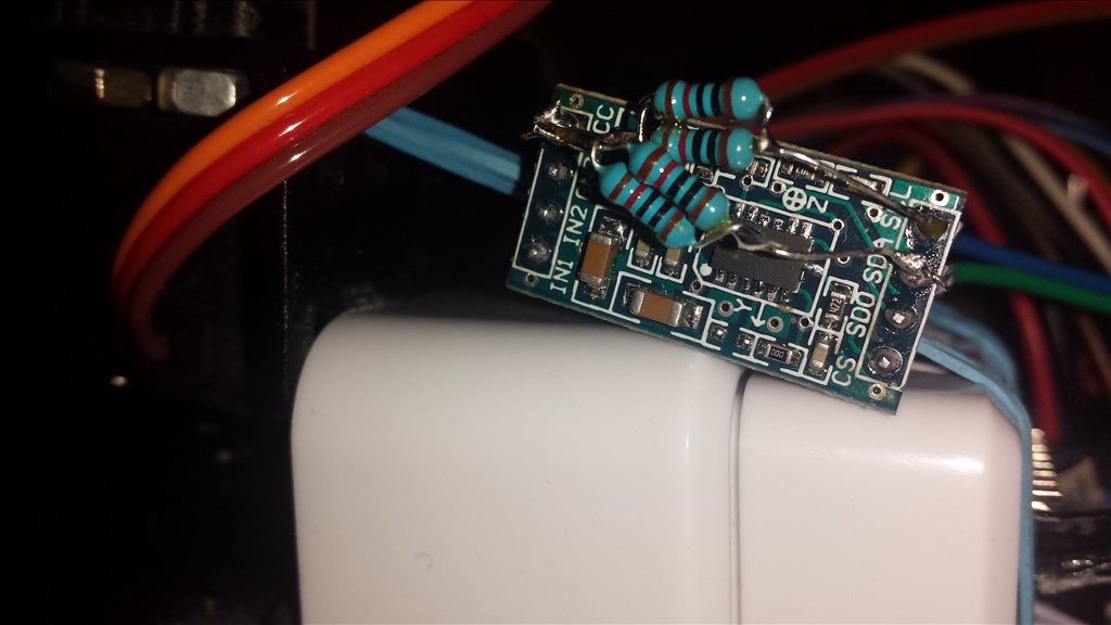
Rich I've re-wired mine but that's not the problem. Nothing to do with the EZ-B board but I noticed if you disconnect the +5v to the MMA7455 it still lights the LED! don't know how that's wired appears to be getting power from the SCL and SDA lines totally weird
A few times in the past I've let the magic smoke out of ICs by plugging them in while the power was turned on.
Is there a chance Rich baked them that way. Mine is working fine even with all the wires being 12 inches.
Bill
I've never plugged them in while it was powered up. Even if I had done so by accident the spare one has been barely used and I am certain has never been plugged in while the power is on.
Also @winstn60 has the same issue.
Mine were working originally when the only control was the MMA control, but when I add the control to Jarvis it either freezes ARC up which requires task manager to kill and a power cycle of the EZ-B or if I add it before connecting to the EZ-B on connection ARC will disconnect as soon as it connects and freeze up with task manager being the only way to kill it.
This happens on 2 different MMAs and on 2 different PCs, while connected direct to the EZ-B or via my I2C header board.
I haven't tried a new project with no controls again yet, I will try that later and see what happens.
For awareness the MMA7455 needs leads at least 6 inches long. I tried short leads 3 inches and it just would not work on the SCL SDA lines. Probably the extra pf on the line helps stop ringing on the pulses. Playing around with pull up resistors just seems to produce inconclusive results
I take it the new update solved this one then? I haven't had chance to check since my PC took a nose dive last night so is currently in bits until the replacement parts come Saturday (was time to upgrade anyway).
My leads are around 4" and it had worked on them without any pull ups. From what I can make out the MMA break out board has pull up resistors on it anyway...
Rich the update has solved most of the issues just a problem remains if the BT connection gets lost for whatever reason. Which is why I haven't closed the question. Bad news about your PC I get very little time to play with this stuff since the arrival of a new baby 2 weeks ago!
Still getting the unresolved forum thread email for this post
You need long leads at least 6 inches for the MMA 7455 to work
Crediting Rich with the fix to see if I can get it to go away
confused