winstn60
United Kingdom
Asked
— Edited
 Virtual Robot
— Display robot image with real-time servo position readouts and basic servo management including servo deletion
Try it →
Virtual Robot
— Display robot image with real-time servo position readouts and basic servo management including servo deletion
Try it →

Interesting...I've always had better results with shorter wires, well it never hurts to try both I guess.
Hey there,
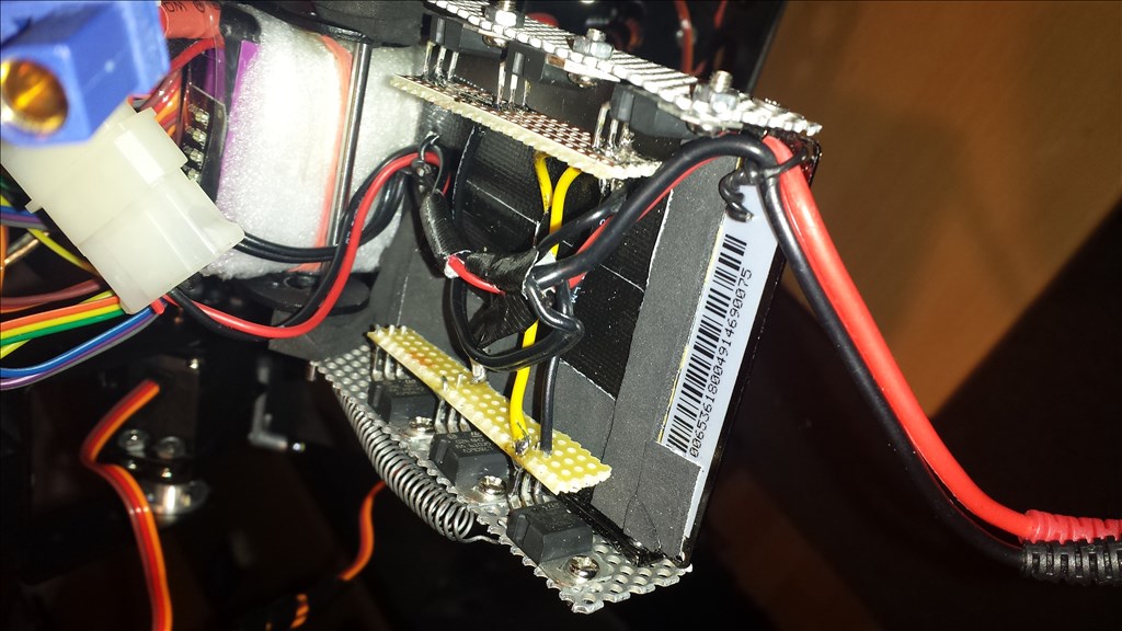
its no car. its a bi-ped. robot and its looking atm like this :
the MAA7455 should go somewhere on the hips.
i have no iphone, but i'll look for something simular for android.
longer cables will be next.
i might soon get me an oscilloscope, so i'll get a closer look to the levels and timing.
@jeremie should i try to "pull up" with 5 V ?
..for that i need to throw in a 7805 for the regulated 5 V
atm I got 6 x 7806 already in it for 6 V, 5 A max for the servos.
so there is :
(they get warm at 5 A max, 2 A average when moving.. they got a small heat-sink by now!)I read a bit about I2c spec's. this might be interesting: (en.wikipedia.org/wiki/I%C2%B2C)
the SDA/SCL levels should be 5V or 3.3V (but it works with something in between) with pull resistors ! the "low level" is under 0.5V.
the I2c network stops, if a device is not working properly. (so we had that already)
....and also by the total bus capacitance of 400 pF, which restricts practical communication distances to a few meters.
I wouldn't suggest pulling up to 5V, as it would damage the accelerometer.
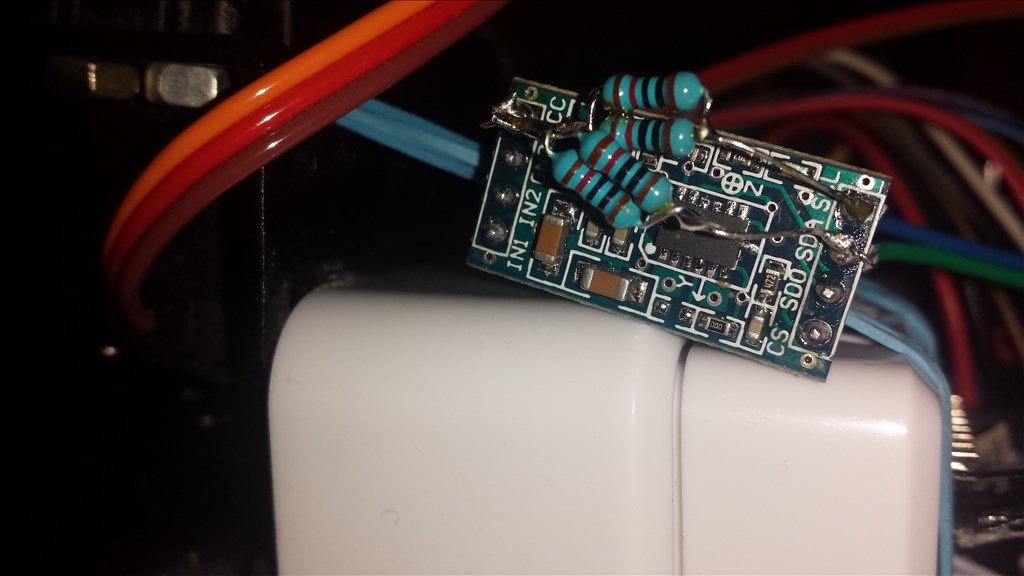
I didn't realize (until you sent the pictures) that you were using that style of application board. That board has pull-ups already on it, as well as a linear voltage regulator.
The voltage regulator will drop the voltage from 3.3V that you are supplying it to somewhere around 2.8V that powers the accelerometer. You may need to by pass the regulator.
I have the same boards at the ezrobot shop, I'll try to do a test tonight.
i thought that. that would be helpful !
i just got 2 new ones on ebay.. this will take a while. maybe mine is just broken. its produced alright, can't see any loose resistors or something..
I was able to get some testing done tonight. I had the MMA7455 board working with the EZ-Bv3 but could not get it working with the v4 yet. There are 4.7K I2C pull-ups on the v3 board so I will need to fiddle around a bit with pull-up values and wire length to work with the MMA7455 board. I know I had it working in the past I just don't remember what I had to do. I think I may have used the LED eyes plugged into another I2C port to leverage the pull-ups it had on board, I will have to do a bit more testing tomorrow.
If you have a v3 board you could test your MMA7455 with it to see if it is working as the v3 board is less picky about I2C.
Hello @Julius,
I have a late Christmas gift for you, I was able to get the MMA7455 accelerometer board to work reliably with the ez-bv4. Here's how I did it:
Used short wires connected from one of the I2C ports on the ez-bv4 to the MMA7455 sensor board
Soldered 4.7Kohm pullups from the SDA and SCL lines to 3.3VDC (these are possibly optional since there seems to be pull-ups on the board)
Soldered a 1nF ceramic capacitor from SDA to GND
Here's some pictures of my setup:
You may not need to, but I removed the voltage regulator from the board and shorted the voltage input and output pins so I didn't have a voltage drop (through the regulator) when I provided 3.3VDC to the VCC pin.
Thank you so much for your effort !
I will go through this today or on weekend.
were is that nice i2c-connector-plug from ?
thanks again! a nice Christmas!
No prob, that I2C connector is from our shop
https://synthiam.com/Shop/AccessoriesDetails.aspx?prevCat=9&productNumber=101
Edit: I forgot to mention that with you current setup you may just need to solder a 1nF cap from SDA to GND on the board and have it work.