
Lcd Display Help
Hey guys.
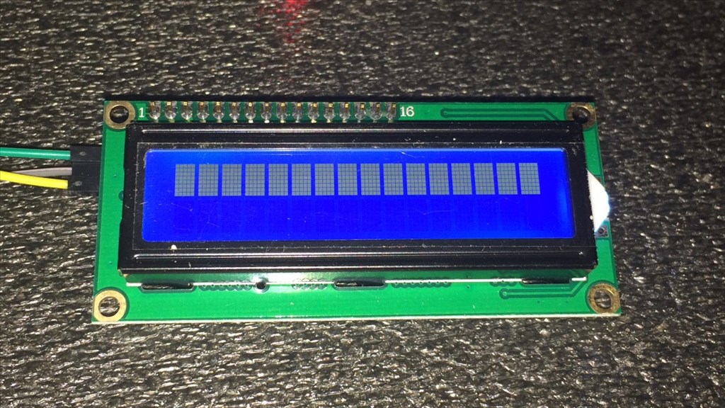
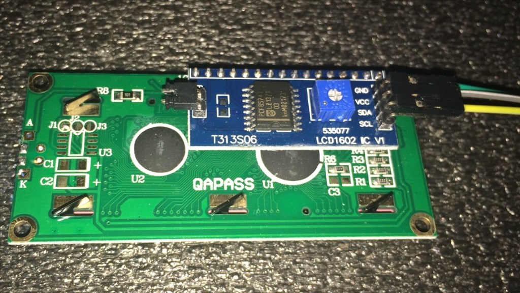
I'm having a little trouble with an LCD display I recently purchased. I have read through some of the posts on the forum to help me get this going, but I need a little more help. I have it connected to D12 going through a 5v regulator. Ground to ground, Vcc to Vcc, and SDA (which I believe to be RX) to a signal pin. It lights up but when I try SendSerial(d12, 9600, "Hello" ) nothing happens. I have also tried a different port and changed baud rates, no change.
Now I believe this is a serial (what I was after) and i2c compatable so it should work. I havn't found a data sheet for it yet but here's a link to it, if it helps. Any ideas what's going wrong, or even if this thing is compatable with the v4? I hope some one can help as I would love to get this working.
Thanks in advance.

Great, thanks guys. I'll give that a try tomorrow and report back.
Cheers.
Steve G, what you could do (as the v4 is embedded in your robot) is to bring an I2C cable from the v4 header socket out to the side of K9 - this way you could plug the LCD05 for debug or displays etc very simply without disturbing the internals.
Tony
UPDATE.
Thanks for the advice Tony . I managed to remove the EZ-B enough to connect an i2c cable without too much bother.
So, after testing he display again using the Melvin script Rich supplied, here are the results...
As you can see, it is an improvement but still too dim to be read properly. I played about changing the last two values which did make subtle differences to the backlight brightness and contrast, but not enough.
Is there a list somewhere that explanes what the number values do? For example...
The first 0 and 0xC6 are board number and i2C device address, but don't know about the rest. Understanding this would help me out heaps.
Steve G, this is what Rich's code line means
0xc6 = I2C address for the LCD05 0 = write to command register 1 = set cursor to home position (top left) 4 = hide cursor 12 = clear screen 19 = backlight on 30 = contrast set ** 255 this is the value of contrast set - try lower value here 31 = brightness set ** 80 this is the value of brightness set - try different value
Hope this helps
Tony
Taken from https://www.robot-electronics.co.uk/htm/Lcd05tech.htm
Note: Serial commands are pretty much the same.
In the example in your post (0,0xC6,0,1,4,12,19,30,255,31,80) it's as follows;
0 = Board Number 0xC6 = I2C address 0 = Null (I believe it escapes previous commands also) 1 = Set cursor to top left 4 = Hide cursor 12 = Clear the screen 19 = Turn on the backlight 30 = Set contrast (followed by 0-255) 255 = Contrast level maximum 31 = Set the brightness (followed by 0-255) 80 = Brightness level 80.
This is as follows; 0 = Board Number 0xC6 = I2C address 0 = Null/Escape from previous commands 3 = Set cursor position (line/column) 4 = Cursor line (this may be your issue, I had 4 line you have 2) 6 = Cursor column
Try this code;
Thanks for the info guys. That was a great help . I have tried various brightness and contrast levels from 10 to 255. Screen brightness, no problem.
Contrast on the other hand, anything from 200 onwards shows the characters, but even at 255 they are just to dim see properly. Getting a bit ticked off with this now. Apart from it possibly being faulty, any final thoughts before I chuck the idea of using it?
Steve G, the only thing I can think of is the display is not getting enough current (hence the dimness) or it is faulty. It is possible to solder on a contrast preset pot (to the three big pads on the opposite side of the connector) that may be worth a try, maybe a 10K pot.
Tony
One thing, and I may be wrong here but isn't the Vcc on the I2C port 3.3v not 5v? If you are powering it from the Vcc of the I2C port it may be worth trying to use a 5V supply from elsewhere, i.e. a digital port (which brings back the Serial issues). My LCD is on my V3 so has 5V Vcc and no problems, I'm yet to try it on the V4.